Clip for heat sink

a heat sink and clip technology, applied in the field of secure devices, can solve the problems of inability to operate the electronic element package and occurrence of functional obstacles, and the inconvenient use of screws to mount or remove the heat sink, and achieve the effect of reducing the risk of damage, reducing the cost of heat dissipation, and improving the efficiency of heat dissipation

Inactive Publication Date: 2006-05-16
HON HAI PRECISION IND CO LTD
View PDF12 Cites 27 Cited by
  • Summary
  • Abstract
  • Description
  • Claims
  • Application Information

AI Technical Summary

Benefits of technology

[0009]Accordingly, an object of the present invention is to provide a clip which can exert balanced forces to a heat sink mounted on an electronic element package.
[0010]Another object of the present invention is to provide a clip which can mount a heat sink to an electronic element package conveniently.

Problems solved by technology

The heat generated by the electronic element package not to be removed away in time will lead to an increase of temperature of the electronic element package and result in instability of operation of the electronic element package and occurrence of functional obstacle.
Therefore, how to dissipate heat fast and effectively has become a problem that must be resolved before a CPU is applied.
However it is distinctly inconvenient to use screws to mount or remove the heat sink.
On the other hand, an accessory tool is needed which results in mounting or removal of the heat sink complicated.
Furthermore, it is difficult to keep the contacting forces between the heat sink and the PCB at the positions where the screws are located equivalent to cause the heat sink to intimately contact the electronic element package.
However, it is inconvenient to hold the slim elastic hook in use.
So, it is not widely used.
However, it is difficult to engage the hanger 200 with the socket connector after clamping portion 140 engages with the socket connector.
Moreover, the hanger 200 is still inconvenient to be held.
Thus, the clip reduces the heat dissipating surface area of the heat sink and therefore decreases the heat dissipating efficiency of the heat sink.
How to mount firmly and conveniently a large dimension heat sink to a PCB by a small operation force becomes a problem which needs overcoming.

Method used


Image

  • Clip for heat sink
  • Clip for heat sink
  • Clip for heat sink

Examples


Embodiment Construction

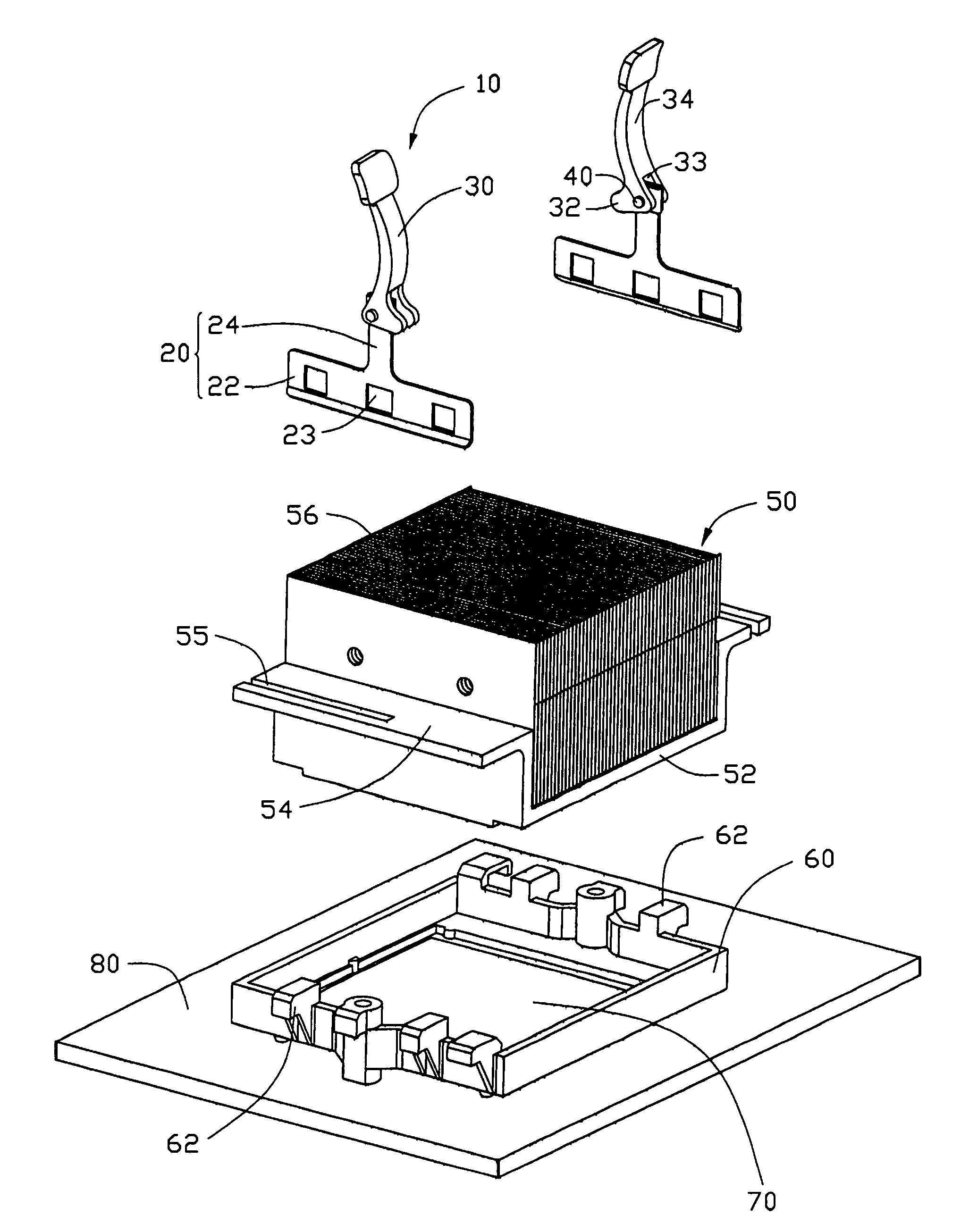
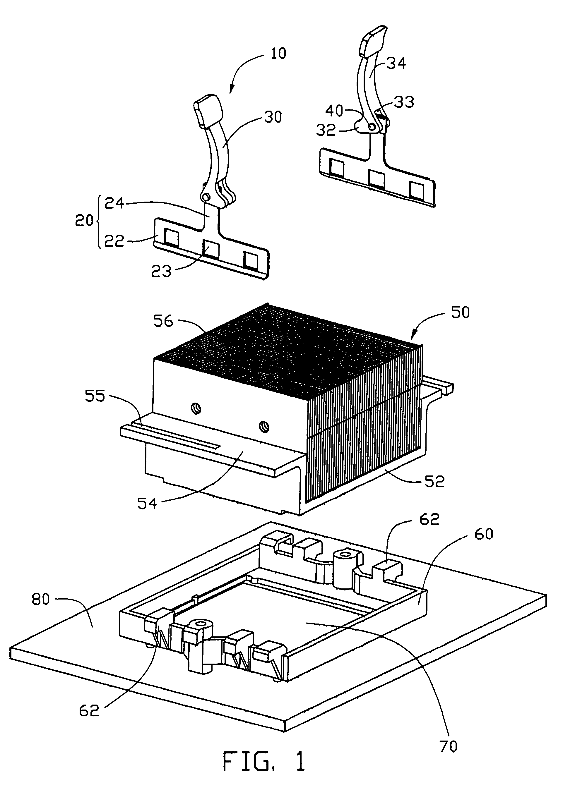
[0017]FIG. 1 shows a pair of clips 10 in accordance with the present invention for mounting a heat sink 50 to an electronic element package 70 which is mounted on a printed circuit board 80 (PCB). A retention module 60 is mounted on the PCB 80 surrounding the electronic element package 70.

[0018]The retention module 60 is a rectangle frame provided with several protrusions 62 protruding outwardly and downwardly from opposite sides thereof.

[0019]The heat sink 50 is made of heat conductive metal and has a U-shaped base (not labeled) for contacting with the electronic element package 70. The base comprises a horizontal portion 52 on which a plurality of fins 56 is formed and two upright portions (not labeled) extending upwardly from opposite sides of the horizontal portion 52. Two platforms 54 extend horizontally and outwardly from the top edges of the upright portions respectively. The two platforms 54 define a pair of parallel slots 55 extending toward each other from two opposite edg...


PUM


Abstract

A clip for heat sink comprises an inverted T-shaped retaining member and an L-shaped operation member pivotably connected to the retaining member. The retaining member has a detaining portion defining several openings and a connecting portion extending from the detaining portion. The operation member has a press portion for bearing against the heat sink and a holding portion for being grasped extending from the press portion. The operation member is capable of being driven to rotate from a first position to a second position to cause the detaining portion to interlock with a retention module provided on a printed circuit board, thereby securing the heat sink to an electronic element package on the printed circuit board.

Description

BACKGROUND OF THE INVENTION[0001]1. Technical Field[0002]The present invention generally relates to a securing device, and particularly relates to a clip for attaching a heat sink to an electronic element package for heat dissipation.[0003]2. Related Art[0004]Development of integrated circuit technology has resulted in the enhanced density of very large scale integrated circuits (VLSI) in electronic element packages, such as a central processing unit (CPU). The electronic element package operates at a very high speed. The faster the electronic element package runs, the more it generates heat. The heat generated by the electronic element package not to be removed away in time will lead to an increase of temperature of the electronic element package and result in instability of operation of the electronic element package and occurrence of functional obstacle. Therefore, how to dissipate heat fast and effectively has become a problem that must be resolved before a CPU is applied.[0005]...

Claims


Application Information

Patent Timeline
Patent Type & Authority Patents(United States)
IPC IPC(8): H05K7/20G06F1/16H01L23/40
CPCH01L23/4093H01L2924/0002Y10T24/44026H01L2924/00
Inventor LEE, HSIEH-KUNLU, CUI-JUNCAO, LING-BO CAO
Owner HON HAI PRECISION IND CO LTD
Why Eureka
Try Eureka