Method and computer program product for determining an area of importance in an image using eye monitoring information

a technology of eye monitoring information and image processing method, which is applied in the field of image processing methods for determining an area of importance in an image, can solve the problems of few images being edited, time-consuming and laborious to achieve, and achieve the effect of more accurate methods

Active Publication Date: 2006-05-16
MONUMENT PEAK VENTURES LLC
View PDF37 Cites 83 Cited by
  • Summary
  • Abstract
  • Description
  • Claims
  • Application Information

AI Technical Summary

Benefits of technology

[0021]The present invention has the advantage that it provides a more accurate method to make determinations about what a photographer or observer finds to be important in an image and for associating that information with the image. This information can then be employed with digital image processing techniques to provide improved image enhancement, image search and retrieval, and other system improvements that benefit from an understanding of the elements of an image that are important to the user.

Problems solved by technology

However, these tools typically require that the user manually designate what is important in each image that is to be edited.
Many users find this process time consuming and, accordingly, few images are edited.
This creates difficulties in associating the data with the images and in preserving the association of the image with such data over the useful life of the image.
While in many circumstances eye gaze direction monitoring may provide an indication of which elements in images are important to a user, in other circumstances, eye gaze direction information can also provide misleading information regarding what is important in an image.
This can lead to erroneous conclusions where the field of view of the camera is shifted during such monitoring.

Method used


Image

  • Method and computer program product for determining an area of importance in an image using eye monitoring information
  • Method and computer program product for determining an area of importance in an image using eye monitoring information
  • Method and computer program product for determining an area of importance in an image using eye monitoring information

Examples


Embodiment Construction

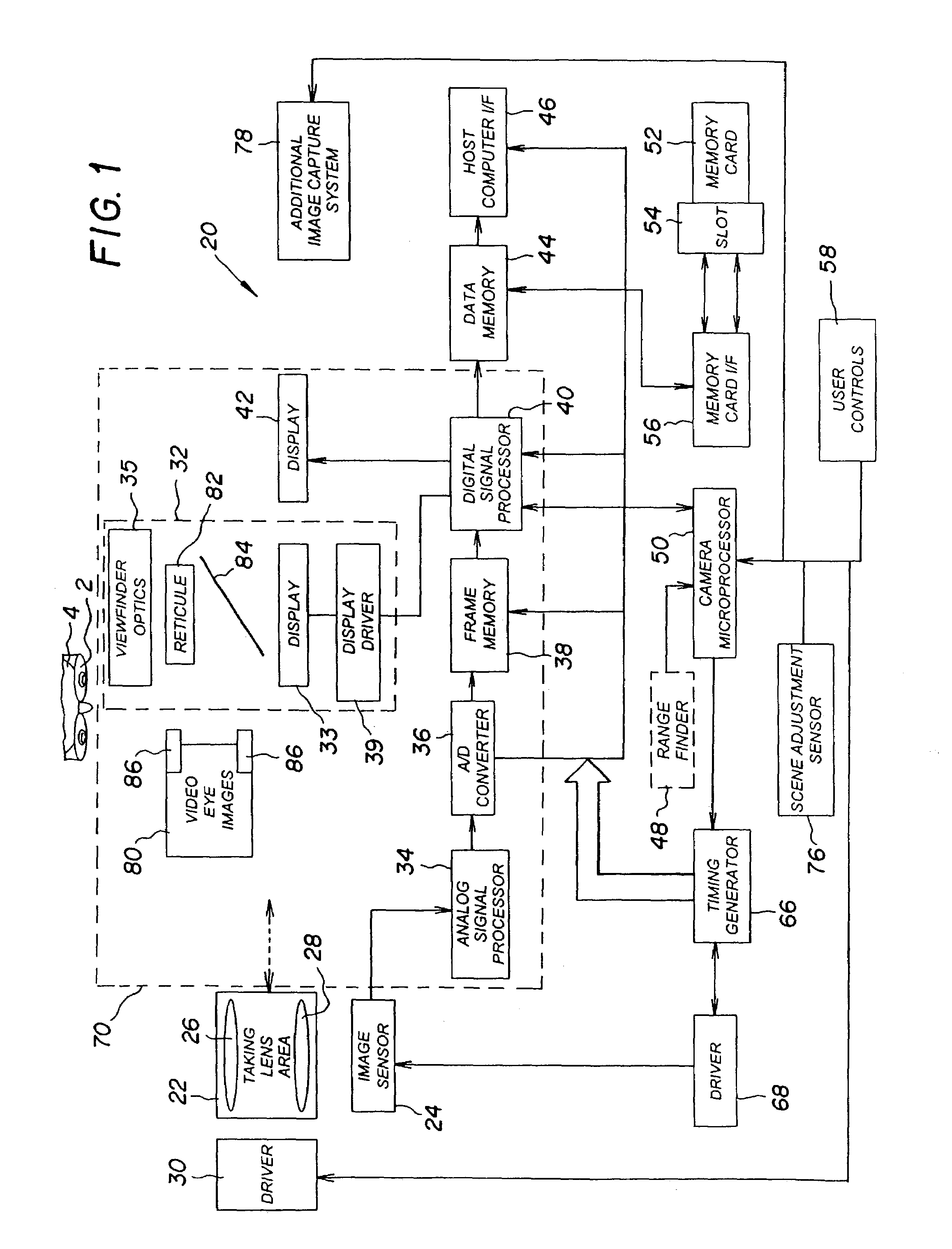
[0037]FIG. 1 shows a block diagram of an embodiment of a camera system 20 for capturing digital still images. As is shown in FIG. 1, camera system 20 includes a taking lens unit 22, which directs light from a subject (not shown) to form an image on an image sensor 24.

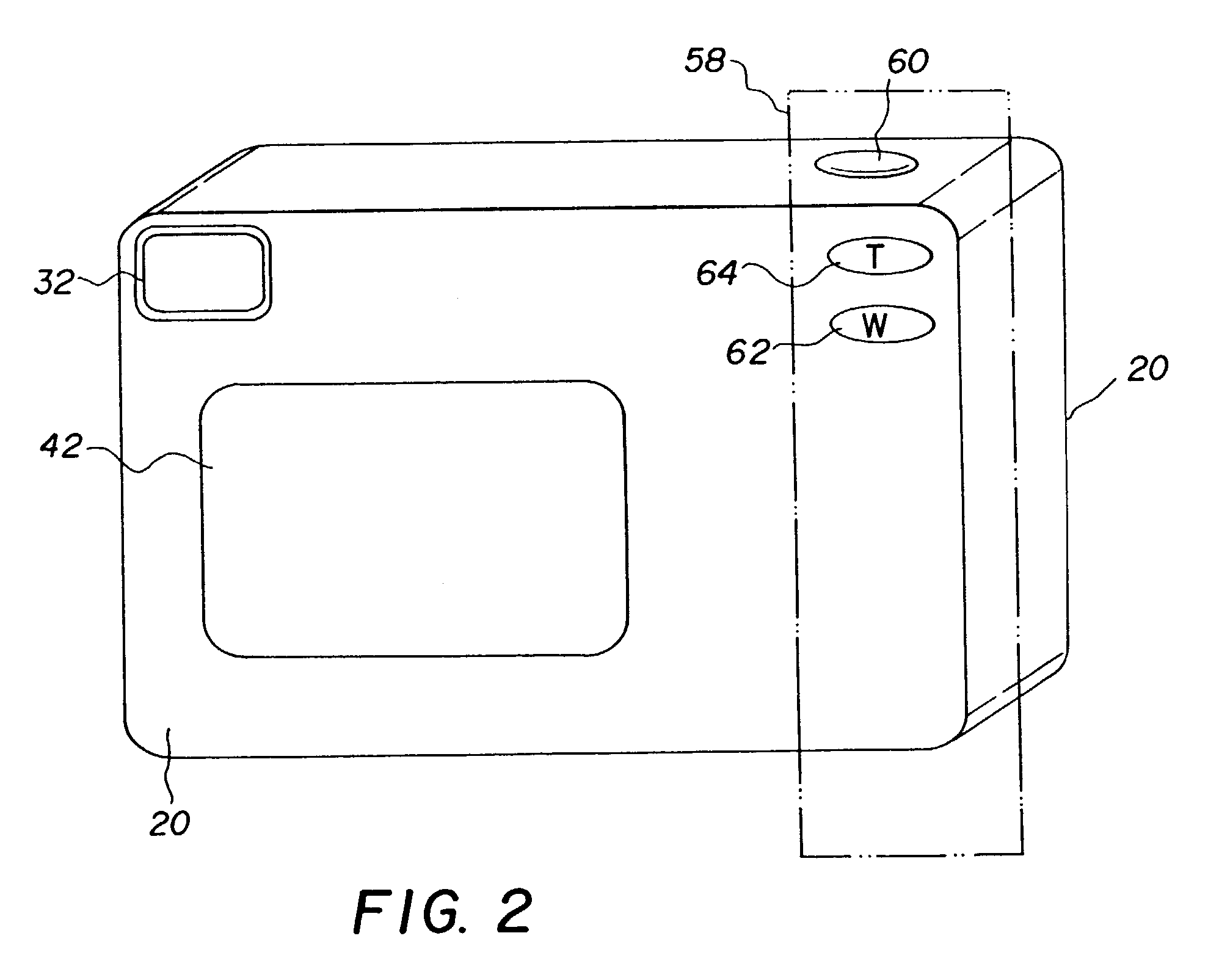
[0038]The taking lens unit 22 can be simple, such as having a single focal length with manual focusing or a fixed focus. In the example embodiment shown in FIG. 1, taking lens unit 22 is a motorized 2× zoom lens unit in which a mobile element or elements 26 are driven, relative to a stationary element or elements 28 by lens driver 30. Lens driver 30 controls both the lens focal length and the lens focus position. A viewfinder system 32 enables a user 4 to compose the image as will be described in greater detail below.

[0039]Various methods can be used to determine the focus settings of the taking lens unit 22. In a preferred embodiment, image sensor 24 is used to provide multi-spot autofocus using what is called the “thr...


PUM


Abstract

A method is provided for determining an area of importance in an archival image. In accordance with this method, eye information including eye gaze direction information captured during an image capture sequence for the archival image is obtained. An area of importance in the archival image is determined based upon the eye information. Area of importance data characterizing the area of importance is associated with the archival image.

Description

CROSS-REFERENCE TO RELATED APPLICATIONS[0001]Reference is made to commonly assigned U.S. patent application Ser. No. 09 / 721,222, entitled “Method For Adding Personalized Metadata to a Collection of Digital Images” filed by Parulski et al. on Nov. 22, 2000; Ser. No. 10 / 036,113, entitled “Method For Creating and Using Affective Information in a Digital Imaging System” filed by Matraszek et al on Dec. 26, 2001; Ser. No. 10 / 036,123 entitled “Method for Using Affective Information Recorded With Digital Images for Producing an Album Page” filed by Matraszek et al., on Dec. 26, 2001, the disclosures of which are incorporated herein by reference. Reference is also made to commonly assigned U.S. patent application Ser. No. 10 / 303,978 entitled “Camera System With Eye Monitoring” filed by Miller et al.; Ser. No. 10 / 304,127 entitled “Imaging Method and System” filed by Fedorovskaya et al.; Ser. No. 10 / 304,037 entitled “Method And System For Creating And Using Affective Information In An Image C...

Claims


Application Information

Patent Timeline
Patent Type & Authority Patents(United States)
IPC IPC(8): G03B17/00G03B7/00A61B3/113G02B7/28G02B27/00G02B27/01G06T1/00G06T7/00G06V10/25H04N1/21H04N5/225H04N5/91
CPCG02B27/017G06K9/0061G06K9/3233G06F3/013H04N1/00331H04N1/2112G06T7/004G02B2027/0138G02B2027/014G02B2027/0187H04N1/00326H04N1/32101H04N2201/3204H04N2201/3225G06T7/70G06V40/193G06V10/25
Inventor MILLER, MICHAEL E.CEROSALETTI, CATHLEEN D.FEDOROVSKAYA, ELENA A.COVANNON, EDWARD A.
Owner MONUMENT PEAK VENTURES LLC
Why Eureka
Try Eureka