Egress 4-bar hinge assembly

a technology for hinge assemblies and windows, applied in door/window fittings, multi-purpose tools, construction, etc., can solve the problems of inability to provide enhanced load capacity and unsatisfactory binding, and achieve the effect of increasing the maximum allowable weight of the window sash, reducing deflection, and increasing load bearing capacity

Inactive Publication Date: 2006-05-23
CALDWELL MFG NORTH AMERICA
View PDF11 Cites 29 Cited by
  • Summary
  • Abstract
  • Description
  • Claims
  • Application Information

AI Technical Summary

Benefits of technology

[0010]The present invention provides a non-handed hinge assembly having enhanced load bearing capacity, while reducing deflection. The present invention provides a hinge assembly such that when in a closed position, the window sash, the window frame and associated weather strip cooperate to maintain a sealed interface. The present hinge assembly increases a maximum allowable weight of the window sash, and further minimizes the likelihood of sash sagging or misalignment of the sash in the frame. The present hinge assembly also provides a “push open” and “pull close” feature which tends to equalize forces on hinge assembly components during operation.
[0011]The present invention provides a hinge assembly such that when the window sash is fully opened, the pivotal axis is positioned to maximize the area of unimpeded opening. For example, in a window sash with a vertical pivotal axis which opens to the left, the pivotal axis, while movable into or out of the plane of the window frame, is near the left hand side of the frame when the window is fully opened. The resulting clearance of the window sash from the right hand side of the frame facilitates egress in the event of an emergency.
[0012]In one configuration, a four-bar hinge assembly in the present invention includes a track, a support extension affixed to the track, the support extension having a planar bearing surface and an integral end cap. A first link is pivotally attached to the support extension at a first pivot point, and a second link is pivotally attached to the support extension at a second pivot point spaced from the first pivot point. In a further configuration, the first and second links include a corresponding tab and capture recess for cooperative engagement as the hinge assembly is disposed in the closed or closing position. The hinge assembly includes a shoe slidably disposed in the track, and a sash bar pivotally attached to the first link and a strut pivotally attached to the sash bar, to the second link and to the shoe. In contrast to prior four-bar hinges having a common first and second pivot point for corresponding first and second links, the present hinge assembly spaces the first and second pivot points and locates the first and second pivot points on the support extension. The support extension is structured to provide enhanced rigidity.
[0013]The present hinge assembly is movable between a closed position and an open position. As the hinge assembly moves towards the closed position, the first and second links cooperate at the tab and capture recess so that an angular displacement of one of the links ensures a corresponding angular displacement of the remaining link. This displacement provides direct assistance to the closure of the hinge assembly and reduces the forces acting on the end cap and thus reduces wear of the end cap. In the closed position, the cooperating tab and capture recess provide additional support in conjunction with the end cap to prevent hinge deflection under high pressure loading, such as wind loads. The cooperative engagement of the first and second links is limited to a portion of the full range of motion to provide a “push open” condition, which reduces contact of the sash flange with the weather strip, therefore reducing wear and potential rolling of the weather strip.
[0014]Pivoting the first and second links about separate spaced-apart pivot points reduces wear as compared with using a shared pivot point. The cooperative link between the first and second links eases movement of the hinge assembly near the closed position when binding would most likely occur during opening and closing.
[0016]The support extension provides a large planar bearing surface to support and allow for parallel rotation the first and second links about the corresponding pivot points while under load from the sash weight. This parallel rotation reduces sash sag and misalignment. That is, the planar bearing surface provides supports for the first and second links and minimizes any tendency of the links to bend. The support extension with integral end cap provides a one piece construction having increased strength at the end cap, which prevents deflection of the end cap during high pressure loading of the sash, such as wind loads.

Problems solved by technology

In addition, and it is typically desirable for the track, sash arm and links to be all aligned when the window sash is closed, as misaligned components can result in long-term bending stresses on pivots which in turn can result in bending and undesirable binding during operation of the hinge.
However, current designs are not able to provide enhanced load capacity while maintaining the limited size dimensions, often dictated by architectural considerations.

Method used


Image

  • Egress 4-bar hinge assembly
  • Egress 4-bar hinge assembly
  • Egress 4-bar hinge assembly

Examples


Embodiment Construction

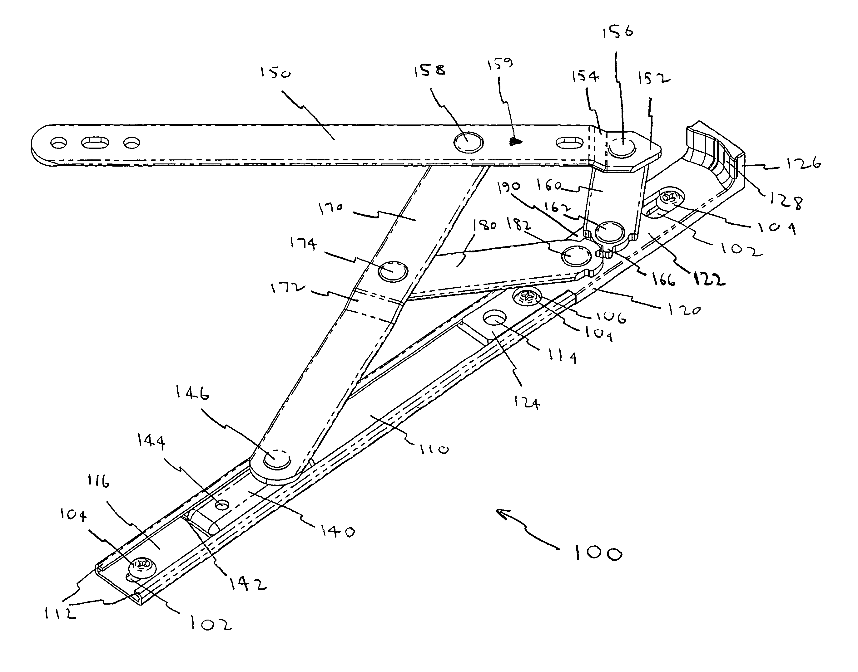
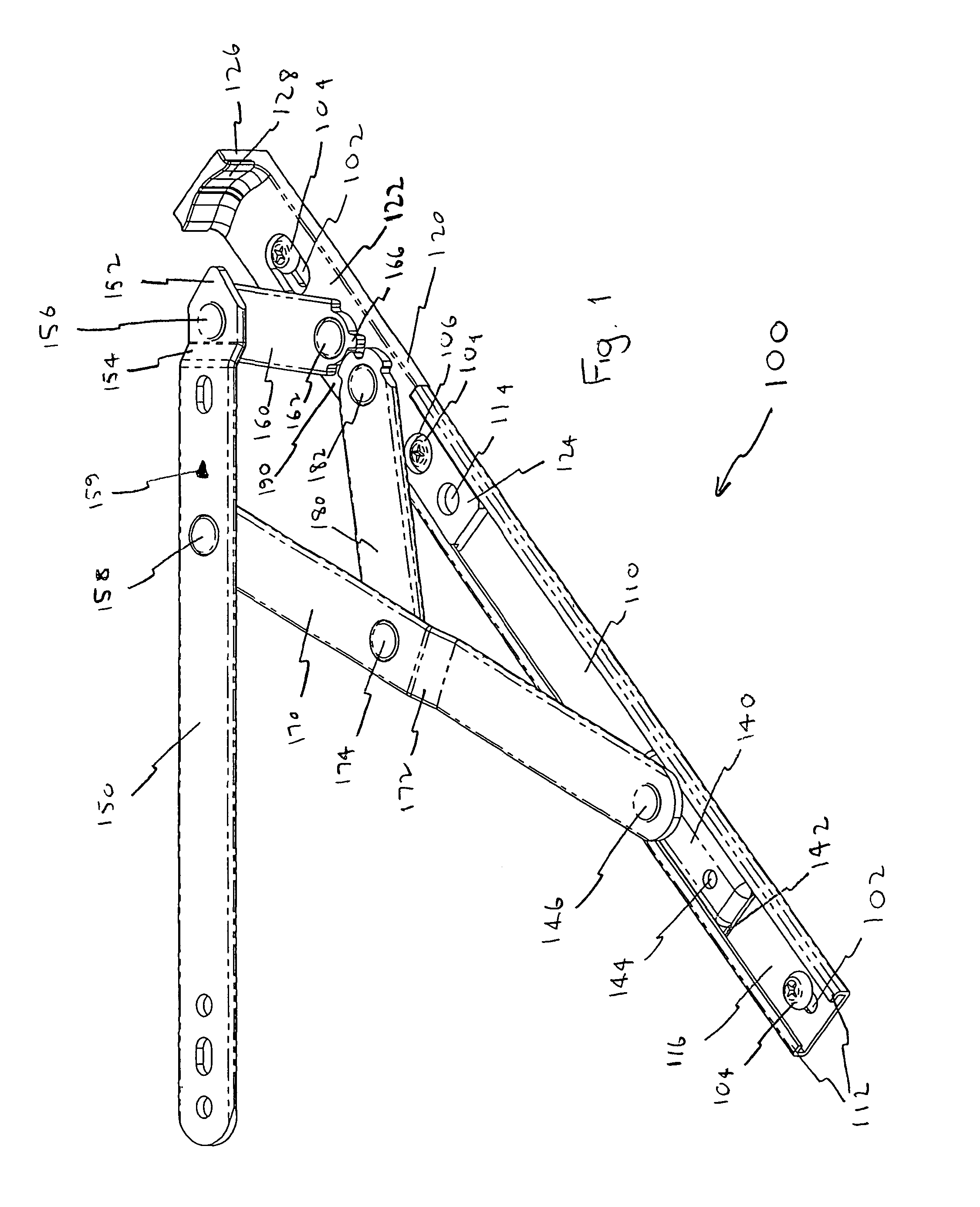
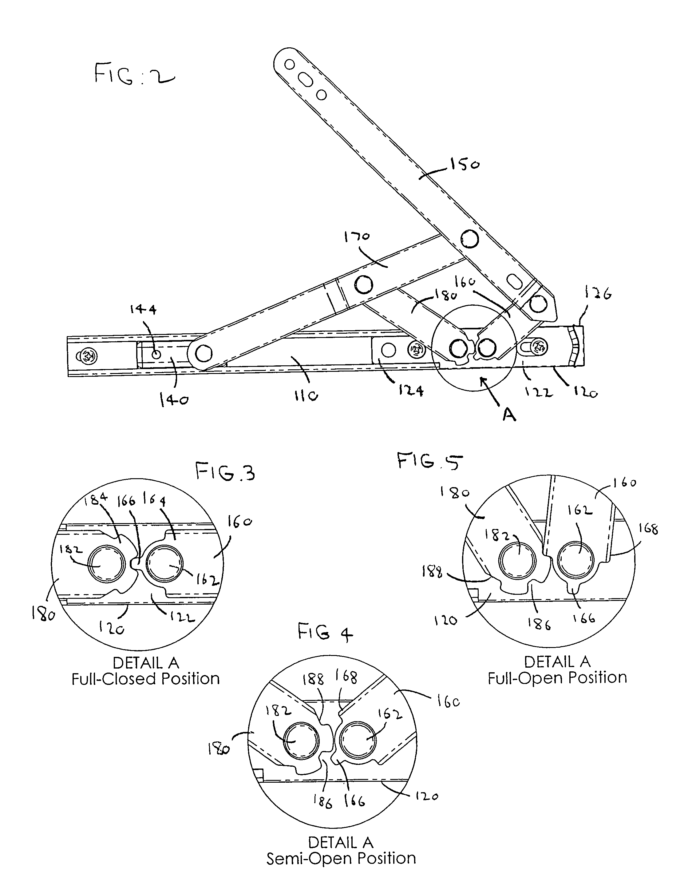
[0029]Referring to FIGS. 1–5, a hinge assembly 100 cooperates with a track 110 having folded side flanges 112. The folded side flanges 112 define a width of the track and a height of the track. The track 110 as a pair of spaced apart ends.

[0030]A support extension 120 is attached to the track 110. The support extension has a bearing surface 122, a flanged end 124 which mates with one end of the track 110, and an end cap 126 opposing the flanged end 124. The flanged end 124 is sized to be received along a length of the track 110 and capture by the flanges 112. In one configuration, the support extension is an integral element, and preferably monolithic. The bearing surface 122 is a substantially planar surface. Further, the bearing surface 122 is sized to have a width substantially equal to the width of the track 10 and a height substantially equal to, or slightly greater than the height of the track. The bearing surface 122 has a predetermined dimension along the longitudinal axis o...


PUM


Abstract

An egress 4-bar hinge assembly having two load-bearing links that pivot about spaced-apart bearing pivot points, wherein an entire length of at least one of the links overlies a planar bearing surface. The two links include a cooperating interface selected to engage through only a portion of the respective range of motions. The hinge assembly includes a support extension to define the bearing surface, wherein the support extension can include an integral end cap.

Description

CROSS-REFERENCE TO RELATED APPLICATIONS[0001]Not Applicable.STATEMENT REGARDING FEDERALLY SPONSORED RESEARCH OR DEVELOPMENT[0002]Not Applicable.REFERENCE TO A “SEQUENCE LISTING”[0003]Not applicable.BACKGROUND OF THE INVENTION[0004]1. Field of the Invention[0005]The present invention relates to hinge assemblies for windows which are arranged to support a window for pivotal movement about either a vertical or a horizontal axis, and more particularly, to a hinge assembly configured to enhance an unimpeded opening area to facilitate egress while providing increased load bearing capacity.[0006]2. Background Art[0007]Hinge assemblies are adapted for the support of casement type windows or projection type windows to permit pivotal movement of the window about a vertical axis or a horizontal axis. The hinge assemblies are typically arranged to allow the pivotal movement of the window from the window frame so that when the window is open, both surfaces of the window are accessible. In additi...

Claims


Application Information

Patent Timeline
Patent Type & Authority Patents(United States)
IPC IPC(8): E05D15/40E05D5/12E05D15/30E05D15/44
CPCE05D15/30E05D5/12E05D15/44Y10T16/5478Y10T16/54052Y10T16/547Y10T16/5476E05Y2600/508
Inventor MUIR, MALCOLM
Owner CALDWELL MFG NORTH AMERICA
Why Eureka
Try Eureka