Pawl mechanism of a ratchet wrench

a ratchet wrench and pawl technology, which is applied in the field of improved pawl mechanism of ratchet wrench, can solve the problems of inconvenient assembly and disassembly of the pawl mechanism, and achieve the effect of enhancing the unit area strength of the teeth of the pawl and the teeth of the ratchet wheel, reducing the wear of the teeth of the pawl and the ratchet wheel, and enhancing the strength of th

Inactive Publication Date: 2006-05-23
LEE CHANG CHUAN
View PDF10 Cites 13 Cited by
  • Summary
  • Abstract
  • Description
  • Claims
  • Application Information

AI Technical Summary

Benefits of technology

[0006]It is therefore a primary object of the present invention to provide an improved pawl mechanism of a ratchet wrench, in which three teeth of the pawl are engaged with three teeth of the ratchet wheel. Therefore, the contact area between the teeth of the ratchet wheel and the teeth of the pawl is enlarged so that the contact pressure created by unit area of the teeth is less than the original contact pressure. Therefore, the unit area strength of the teeth of the pawl and the teeth of the ratchet wheel is enhanced. Accordingly, the wearing of the teeth of the pawl and the teeth of the ratchet wheel is reduced.
[0007]It is a further object of the present invention to provide the above pawl mechanism in which a cylindrical boss of the pawl is located in a locating hole of the wrench main body to easily assemble, disassemble and locate the pawl. Accordingly, the assembling time is shortened and the assembling procedure is facilitated.

Problems solved by technology

Therefore, it is inconvenient to both assemble and disassemble the pawl mechanism.

Method used


Image

  • Pawl mechanism of a ratchet wrench
  • Pawl mechanism of a ratchet wrench
  • Pawl mechanism of a ratchet wrench

Examples


Embodiment Construction

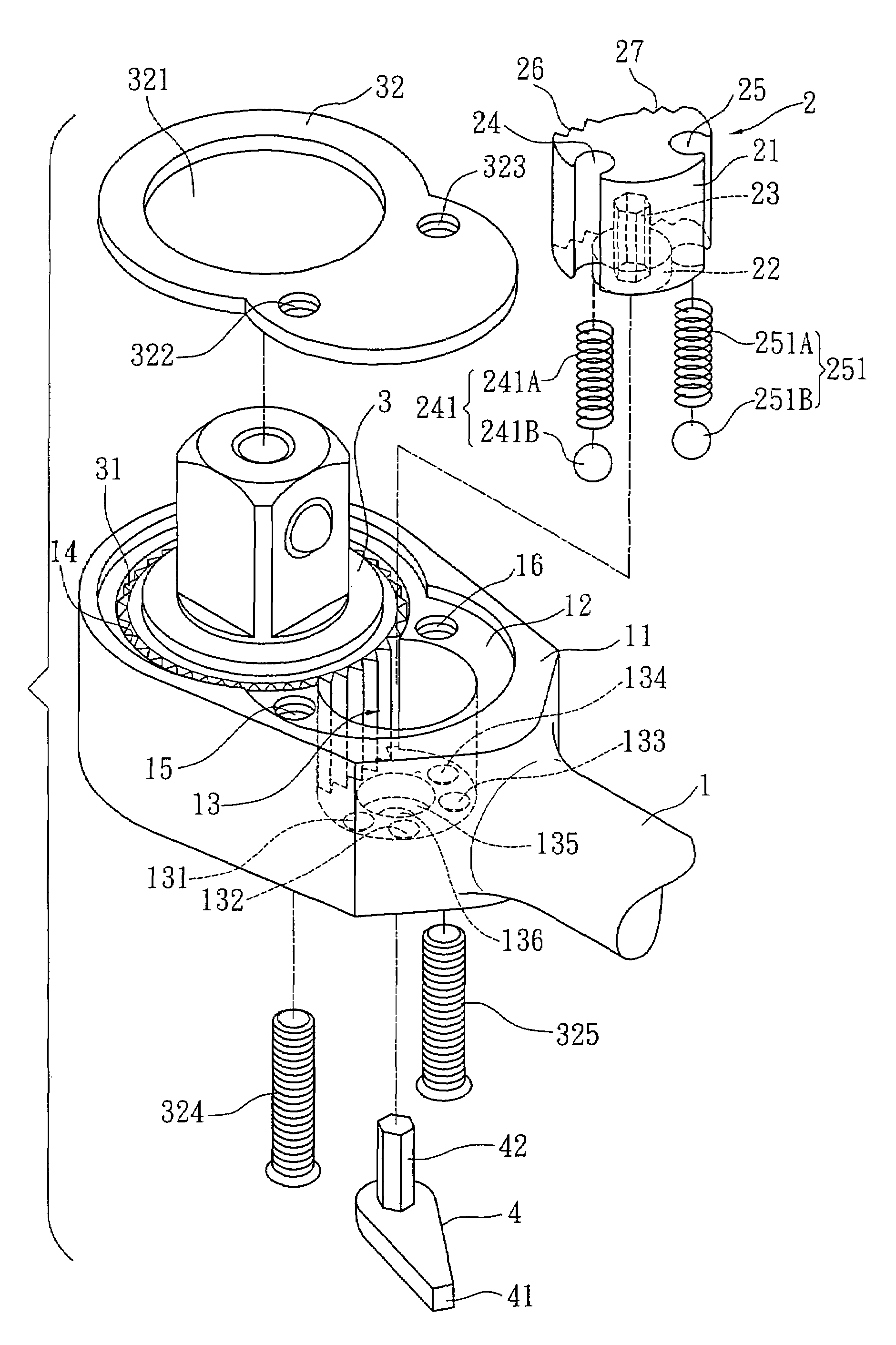
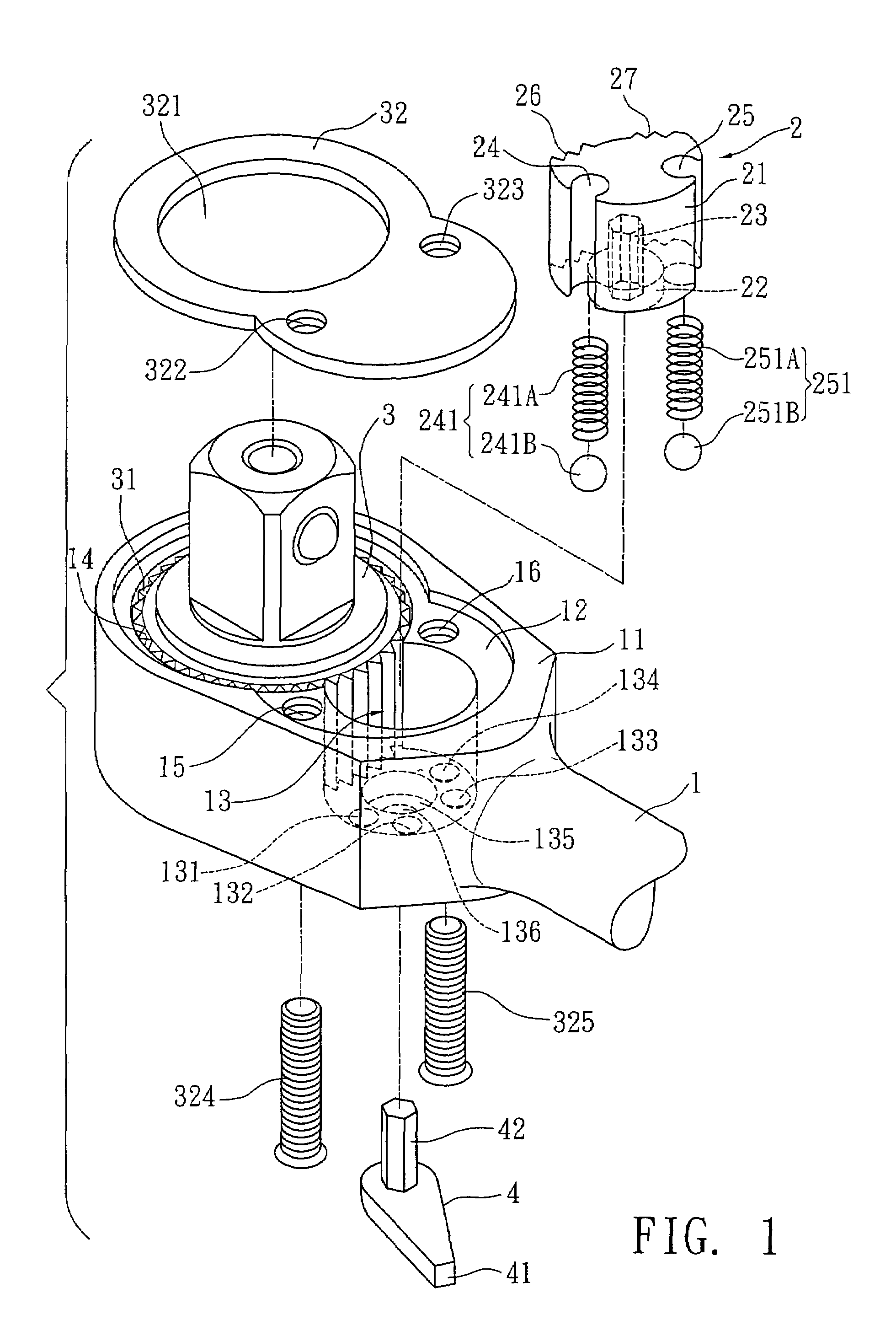
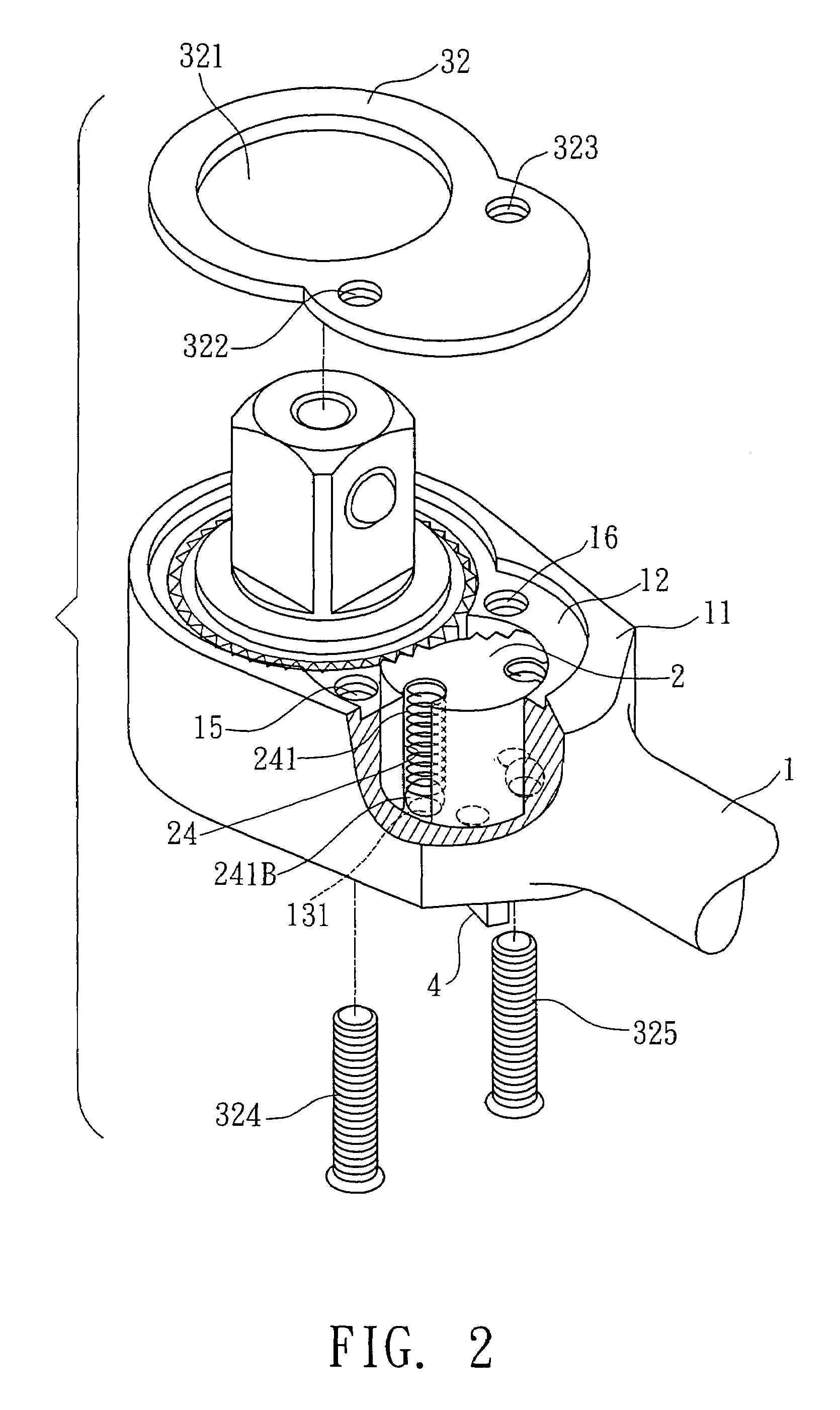
[0021]Please refer to FIGS. 1 and 2. According to a first embodiment, the pawl mechanism of the ratchet wrench of the present invention includes a wrench main body 1, a pawl 2, a ratchet wheel 3 and a shift member 4.

[0022]The wrench main body 1 has a head section 11 formed with a first receiving cavity 12 composed of a first recess 13 and a first receptacle 14. The first receiving cavity 12 is formed with a first thread hole 15 and a second thread hole 16. The bottom of the first recess 13 is formed with a first engaging recess 131, a second engaging recess 132, a third engaging recess 133 and a fourth engaging recess 134. In addition, the bottom of the first recess 13 is formed with a locating hole 135 and a through hole 136.

[0023]The bottom 21 of the pawl 2 has a cylindrical boss 22. The bottom face of the cylindrical boss 22 is formed with a second receiving cavity 23. Two sides of the pawl 2 are respectively formed with a first engaging channel 24 and a second engaging channel 2...


PUM


Abstract

A pawl mechanism of a ratchet wrench, including a wrench main body, a pawl, a ratchet wheel and a shift member. Four engaging recesses are formed on a bottom of a first recess of the wrench main body. A first engaging channel and a second engaging channel are respectively formed on two sides of the pawl corresponding to two of the four engaging recesses of the wrench main body. A spring and a steel ball are disposed in each of the engaging channels, whereby the steel balls can be located in the corresponding engaging recesses of the wrench main body.

Description

BACKGROUND OF THE INVENTION[0001]The present invention is related to an improved pawl mechanism of a ratchet wrench.[0002]FIG. 7 shows a pawl mechanism of a conventional ratchet wrench. The main body 6 of the wrench is formed with a receiving cavity 64 having a recess 61. A compression spring 62 and a dog 63 are embedded in the recess 61. A pawl 7 and a ratchet wheel 8 are mounted in the receiving cavity 64 of the main body 6. The spring 62 serves to resiliently push the dog 63 to abut against one face of the pawl 7. The teeth of the pawl 7 are engaged with the ratchets of the ratchet wheel 8 to dog the ratchet wheel 8.[0003]The above pawl mechanism of the conventional ratchet wrench has some shortcomings as follows:[0004]1. The spring 62 serves to resiliently push the dog 63 to abut against simply one face of the pawl 7. The force exerted onto the pawl 7 by the dog 63 is uneven.[0005]2. When assembling the ratchet wrench, the spring 62 and the dog 63 are embedded in the recess 61 o...

Claims


Application Information

Patent Timeline
Patent Type & Authority Patents(United States)
IPC IPC(8): B25B13/46
CPCB25B13/463
Inventor LEE, CHANG CHUAN
Owner LEE CHANG CHUAN
Why Eureka
Try Eureka