
Split flow edi apparatus for treating second pass ro permeate water with high flow rate

a technology of ro permeate water and edi apparatus, which is applied in the direction of liquid/fluent solid measurement, fluid pressure measurement, peptides, etc., can solve the problems of resin volume inside the dilute chamber and concentrate chamber that cannot increase the flow rate, and limit the conditions requiring additional pretreatment that may be uneconomical, so as to achieve high product flow rate and mechanical leakage , the effect of high product flow ra

Active Publication Date: 2012-04-05
AQUATECH INT LLC
View PDF3 Cites 1 Cited by
  • Summary
  • Abstract
  • Description
  • Claims
  • Application Information

AI Technical Summary

Benefits of technology

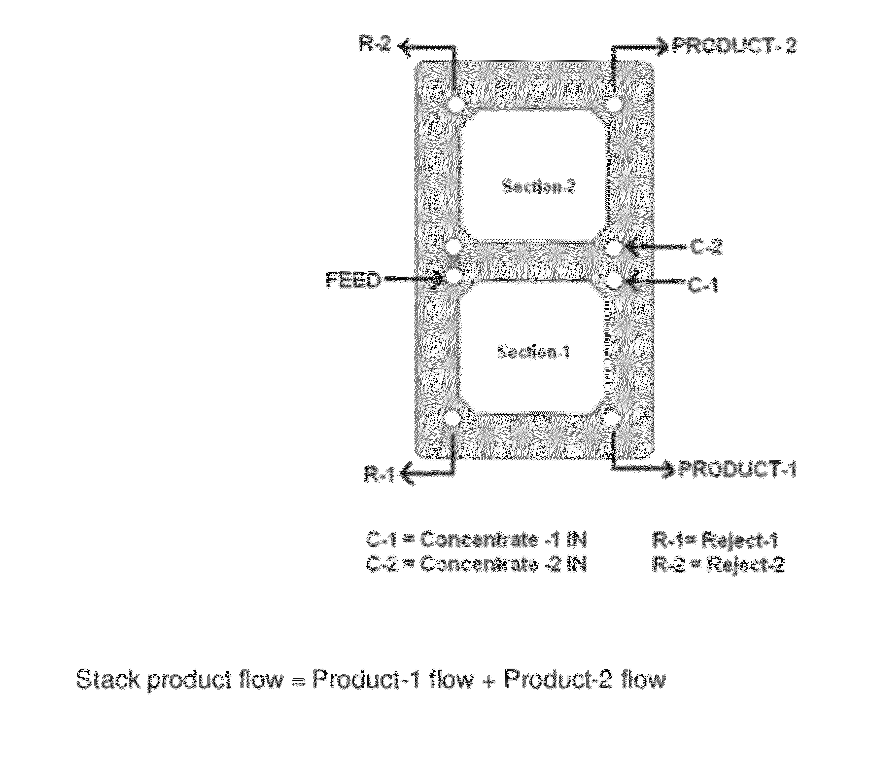
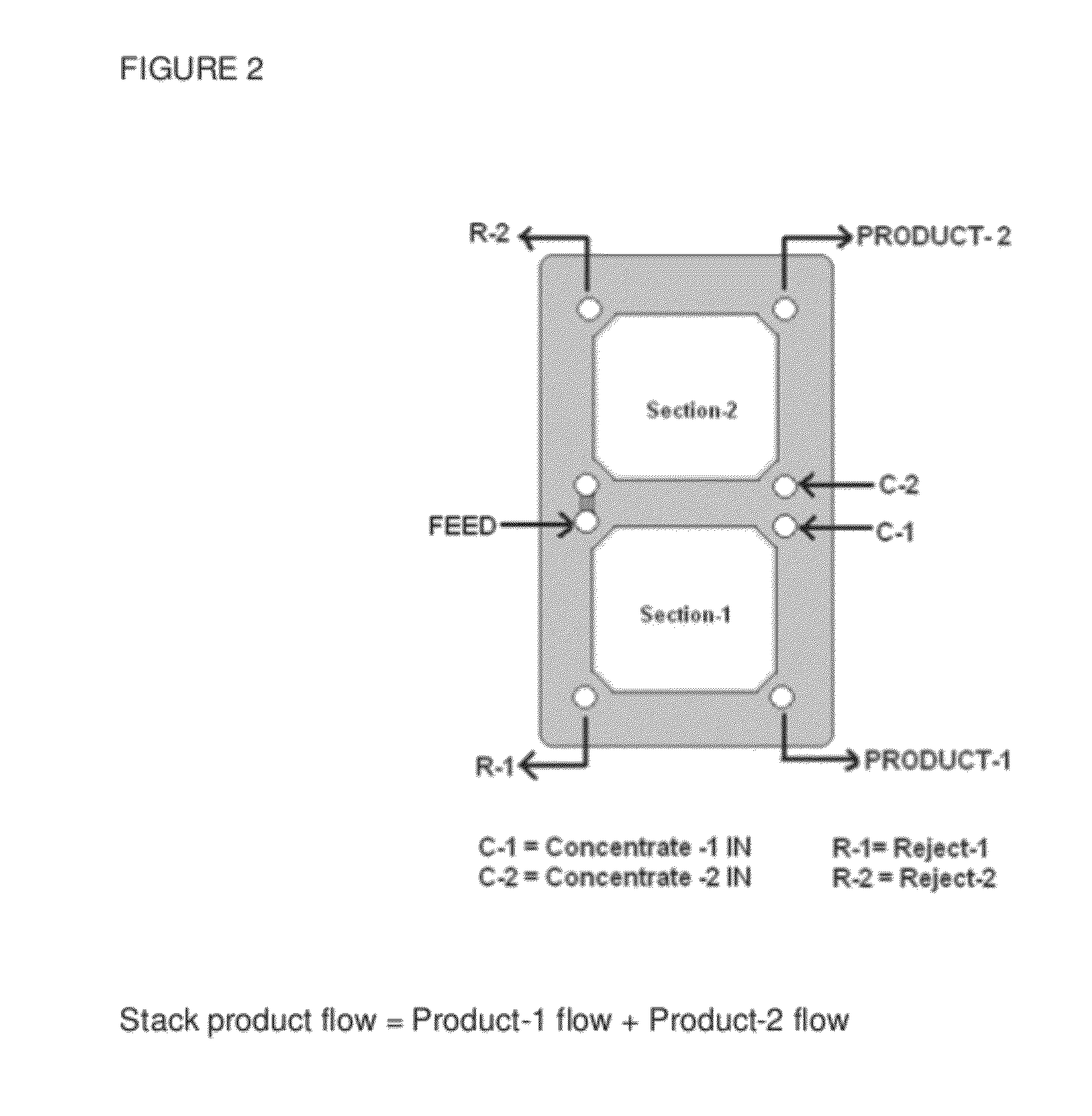
[0027]To attempt to overcome the limitation of high pressure drop, more cell pair or increased unit area for high flow rate and mechanical leaks through EDI apparatus, we provide the unique EDI apparatus design reported herein. Embodiments of the invention may overcome one or more of the limitations, and may be capable of producing high product flow rate in the ranges of 5.0 m3 / hr to 10.0 m3 / hr for treating 2nd pass RO permeate water to produced ultra pure level, more than 1.0 MOhms / cm product (generally 10 to 16 MOhms·cm product water) with only 30-35 cell pairs. The output product flow rate through each dilute camber of embodiments of this new EDI apparatus is 150 to 280 LPH which is almost double of the conventional EDI apparatus. The design of the new EDI apparatus has the flexibility to operate in conventional mode if single pass RO permeate water is provided as feedwater.

Problems solved by technology

This leads to the formation of dilute chambers and concentrate chambers.
The resin volume inside the dilute chambers of these EDI apparatus does not allow increase in the flow rate due to high pressure drops, mechanical leaks or mechanical strength of the apparatus.
The scaling ions (like Ca2+, Mg2+, CO3, SiO2, etc) have big role to play in any EDI operation and have been the cause for limiting conditions requiring additional pretreatment that may be uneconomical in many cases.
This makes the system costly and therefore unattractive for use.
Scaling is not a major concern, and the rate of effective in-situ media regeneration is the main criterion to govern the process and higher product quality can be easily achievable even with high flow rate but the main limitation is the higher pressure drop across the dilute chamber in regular flow mode.

Method used

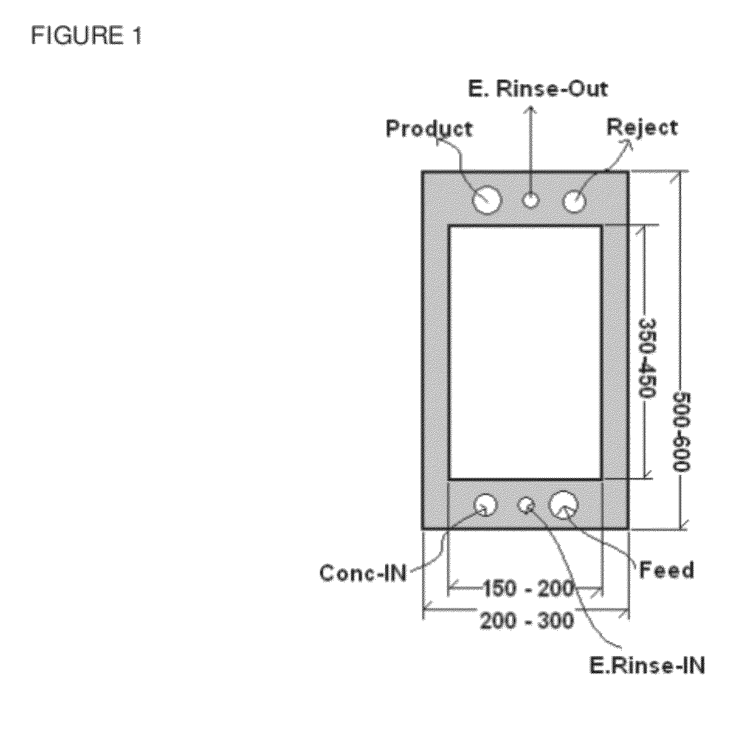

Image

  • Split flow edi apparatus for treating second pass ro permeate water with high flow rate
  • Split flow edi apparatus for treating second pass ro permeate water with high flow rate
  • Split flow edi apparatus for treating second pass ro permeate water with high flow rate

Examples


examples

[0069]A series of trials were conducted on new design EDI apparatus with 30-35 cell pair configuration.

example 2

[0079]One new split flow design EDI apparatus with 30-cell pair was assembled with the following components:[0080]Dilute chambers—30 in number with resin media[0081]Concentrate chambers—31 in number with conducting mesh[0082]Electrode chambers—O2 in number[0083]End plates—O2 in number[0084]Electrode: anodeTitanium and Cathode—SS-316[0085]Membrane: Heterogeneous Ion exchange membranes[0086]Effective Membrane area of dilute chamber—4.32 m2

[0087]The EDI apparatus has been tested for following product flow rate and feed FCE load[0088]A—Product flow rate*=5.0 m3 / hr (5000 LPH) with feed FCE of 9 to 10 (table-1)[0089]B—Product Flow rate*=6.0 m3 / hr (6000 Lph) with Feed FCE of 1.0 to 10 (table-2)[0090]C—Product flow rate*=7.0 m / hr (7000 Lph) with Feed FCE of 1.0 to 10 (table-3)

Note: * product Flow Rate=Product-1 flow+product-2 flow)

[0091]The stack product quality in above three flow conditions is always more than 10 MOhms·cm. The applied current is maintained in between 2.0 amps and 3.0 amp...

example-3

[0094]Another New Split Flow EDI apparatus with new design components was assembled first with 30-cell pairs and tested for 587 hours in 5.0 m3 / hr to 7.0 m3 / hr product flow rate and then 5 more cell pair added to the apparatus to make it 35-cell pair apparatus and continue the testing up to 857 hours with product flow rate of 6.0 m3 / hr to 10.0 m3 / hr with 2nd pass RO permeate water having less than 10 μS / cm FCE load.

[0095]The EDI apparatus configuration of example-3 is[0096]Dilute chambers—30-35 nos with resin media[0097]Concentrate chambers—31-36 nos with conducting mesh.[0098]Electrode chambers—O2 nos.[0099]End plates—O2 number[0100]Electrode: anodeTitanium and Cathode—SS-316[0101]Membrane: Heterogeneous Ion exchange membranes[0102]Effective Membrane area of dilute chamber—4.32 m2 (30-cell pair) to 5.04 m2 (35 cell pair)

[0103]The EDI apparatus has been tested for following product flow rate[0104]D—Product flow rate*=5.0 m3 / hr (5000 LPH) to 7.0 m3 / hr (7000 LPH) (table-5)[0105]E—Pro...


PUM

PropertyMeasurementUnit
feedwater conductivityaaaaaaaaaa
conductivityaaaaaaaaaa
flow rateaaaaaaaaaa

Abstract

We report an electro-deionization (EDI) device having split flow arrangement for the purification of second pass RO permeate water with high flow rate in which the feed water is fed through the center port and is diverted into each section of dilute chamber with equal flow rate, producing two product streams. The EDI device has concentrate chambers adjacent to dilute chambers in two sections of the stack, allowing independent flow through the separate sections. The split flow design reduces resin bed depth requirement for processing of second pass RO permeate water. This results in higher flow rate through the stack, elimination of the pressure drop limitation, and reduction of power consumption per unit volume of water.

Description

CROSS-REFERENCE TO RELATED APPLICATIONS[0001]This application claims priority to U.S. Provisional Patent Application No. 61 / 428,413, filed on Dec. 30, 2010, and to Indian Patent Application No. 2384 / DEL / 2010, filed on Oct. 4, 2010. Both of those applications are incorporated by reference as if fully rewritten herein.BACKGROUND OF THE INVENTION[0002]1. Field of the Invention[0003]Embodiments of the invention relate to electro-deionization methods and apparatus.[0004]2. Background of the Related Art[0005]An Electro-Deionization apparatus (EDI) is a device that removes the dissolved impurities of reverse osmosis (“RO”) permeate water with the help of resin media, ion exchange membrane and DC current. The EDI process is a continuous process as it does not need chemicals such as acid and caustic for regeneration of resin media and membranes. The resin media is regenerated during the purification of water due to continuous water splitting occurring inside the EDI apparatus. Splitting of H...

Claims


Application Information

Patent Timeline
Patent Type & Authority Applications(United States)
IPC IPC(8): B01D61/48C02F1/469B01D61/52
CPCB01D61/025B01D61/48B01D61/485B01D61/58C02F1/441C02F1/4695C02F9/00C02F2209/05C02F2201/4618C02F2201/4611B01D61/50B01D2313/14B01D2313/345
Inventor CHIDAMBARAN, RAVIBISHT, NARENDRA SINGHRAINA, PAVAN
Owner AQUATECH INT LLC
Learn More