Identification device detection using multiple signal combination

a detection device and signal combination technology, applied in the field of object identification systems, can solve the problems of less expensive identification devices being used, and achieve the effects of accurate and reliable detection of identification devices, reduced detection cost, and high detection probability

Inactive Publication Date: 2006-05-23
RF CODE
View PDF2 Cites 61 Cited by
  • Summary
  • Abstract
  • Description
  • Claims
  • Application Information

AI Technical Summary

Benefits of technology

[0006]By selecting several antenna patterns, each contributing to a respective binary result, a logical combination of binary results may provide detection with a higher probability of detecting an identification device that is within range of the one or more selected antennas (an in-range identification device) and / or a lower probability of detecting an identification device that is not within range of the one or more selected antennas (a not-in-range identification device).
[0007]Consequently, inter alia, more accurate and more reliable detection of identification devices may be obtained and more rapid determination of an unknown population of identification devices may be obtained.
[0008]In an object identification system according to various aspects of the present invention, a communication link utilizing one of the selected antennas may be used to provide power to identification devices via a transmitted signal. By using a selected antenna for this function, the probability of an in-range identification device absorbing sufficient power from the transmitted signal increases and / or the probability of a not-in-range identification device absorbing sufficient power from the transmitted signal decreases. Further, a communication link utilizing one of the selected antennas may be used for communicating with identification devices by transmitting to them, receiving from them, or both transmitting and receiving. By using one or more selected antennas and / or a selected method of combining binary results determined from use of one or more of the selected antennas, the probability of communicating with an in-range identification device without error is increased and / or the probability of communicating with a not-in-range identification device without error is decreased. Providing power and / or communicating without error may be made less dependent on the orientation of the antenna of an in-range identification device. Consequently, more accurate and more reliable detection of identification devices may be obtained and communication with an initially unknown number of identification devices may take less time. Less expensive identification devices may be utilized where expense incurs from multiple or omnidirectional antenna structures on the identification device.
[0009]Use of more than one link for powering and / or communicating with identification devices may be used to advantage in environments where multiple signal paths may link an identification device with a plurality of selected antennas. By combining the respective binary results associated with respective reflected radio frequency signals, more accurate and more reliable detection of identification devices may be obtained and communication with an initially unknown number of identification devices may take less time.
[0010]Use of more than one link for powering and / or communicating with identification devices may be used to advantage in environments where multiple identification devices may transmit simultaneously, causing a so-called collision. By selecting antennas for powering or communicating, a subset of identification devices may be enabled to transmit. The probability of a collision may be decreased and more accurate and more reliable communication with an initially unknown number of identification devices may take less time.

Problems solved by technology

Less expensive identification devices may be utilized where expense incurs from multiple or omnidirectional antenna structures on the identification device.

Method used


Image

  • Identification device detection using multiple signal combination
  • Identification device detection using multiple signal combination
  • Identification device detection using multiple signal combination

Examples


Embodiment Construction

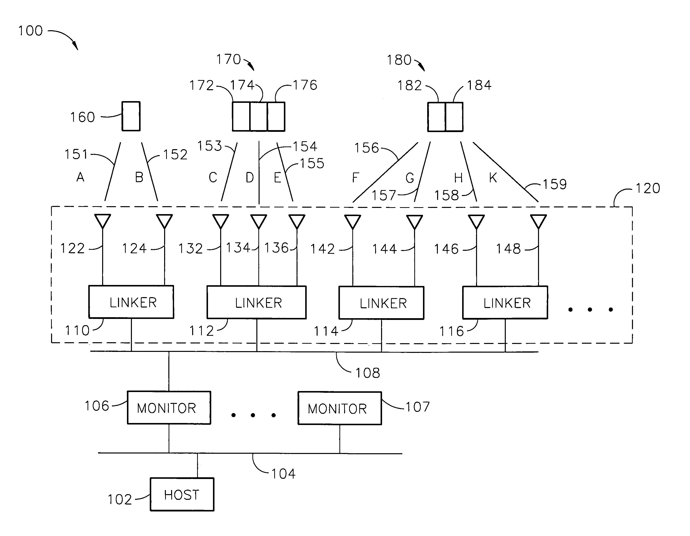
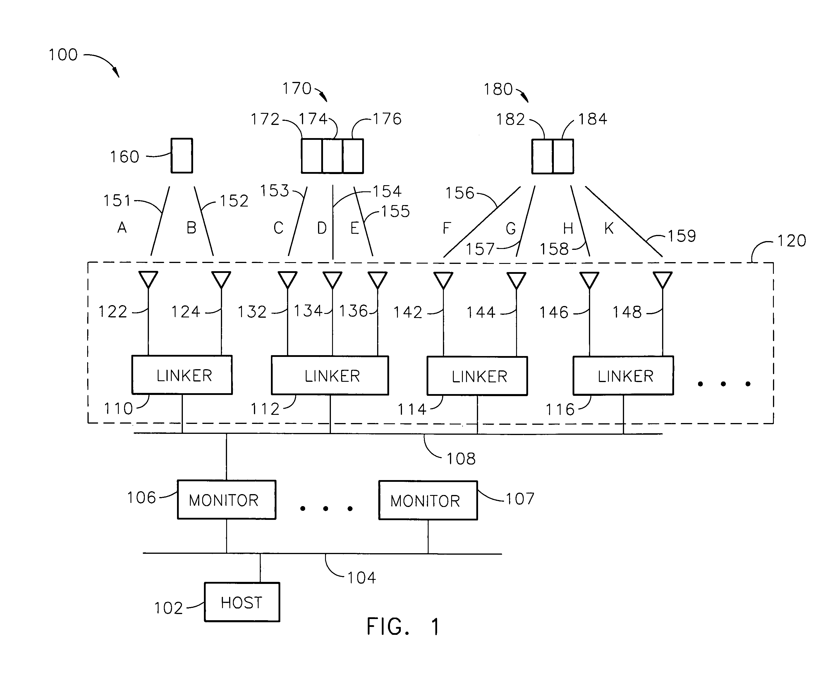
[0020]An object identification system, according to various aspects of the present invention, provides communication between a monitor and an object, while the monitor and object are within communicating range. Each object, for example, may include a radio frequency identification (RFID) device having an antenna used for communication. Communication, as used herein, may be used to accomplish one or more purposes including: (a) to detect presence of an identification device (e.g., to locate an object as in a zone), (b) to provide operative power to an identification device, (c) to determine an identification device identification, (e) to receive data from an identification device, or (f) to send data to one or more identification devices. Transmitted power levels may vary according to the range suitable for the communication. For example, objects may be detected at a comparatively lower transmitted power level to avoid collisions as discussed above. Communication may be accomplished ...


PUM


Abstract

A method for determining whether an radio frequency identification (RFID) device is detected, includes: (a) selecting a plurality of different antenna patterns from a predetermined multiplicity of antenna patterns; (b) determining a plurality of binary results; (c) selecting, from a plurality of predetermined methods, a method for forming a logical combination; and (d) determining that the identification device is detected by forming a logical combination of the plurality of binary results according to the selected method. Each binary result is responsive to whether a respective communication link provides a respective signal having a respective amplitude exceeding a respective threshold. Each communication link is operative in accordance with at least one of the selected antenna patterns.

Description

FIELD OF THE INVENTION[0001]Embodiments of the present invention relate to object identification systems of the type having multiple transmitting and receiving devices that share a common communication medium; and, to methods for establishing communication in the presence of large numbers of such devices especially where communication is subject to reception of signals on multiple paths.BACKGROUND OF THE INVENTION[0002]Conventional data communication systems have been applied to accomplish object identification using the medium of radio broadcast. Such radio frequency identification (RFID) systems find application in the fields of materials handling, inventory control, and generally in the field of tracking personnel, objects, and animals. Identification devices are of three known types: passive, active identification devices of the beacon type, and active identification devices of the transceiver type. In an exemplary arrangement, a system may include an interrogator (or system rec...

Claims


Application Information

Patent Timeline
Patent Type & Authority Patents(United States)
IPC IPC(8): H04Q1/00G06K17/00G06K7/00H04B5/02
CPCG06K7/0008
Inventor KOERNER, STEVE J.
Owner RF CODE
Why Eureka
Try Eureka