Color printer calibration

a color printer and calibration technology, applied in the field of image processing, can solve the problems of paper stretching and wrinkles, ink or other colorants applied to the substrate, and the inability to achieve etc., and achieve the effect of facilitating the generation of separate sets of tone scale transformations

Inactive Publication Date: 2006-05-23
EASTMAN KODAK CO
View PDF33 Cites 54 Cited by
  • Summary
  • Abstract
  • Description
  • Claims
  • Application Information

AI Technical Summary

Benefits of technology

[0007]In accordance with one aspect of the present invention, a method is provided for determining the upper ink limit of a printing system on a specified substrate. This determination is based on a subjective evaluation of acceptable thresholds for bleed, cockle, show through, and image density. The method works in conjunction with a predefined test pattern printed on the specified substrate at fixed printing parameters, such as speed, dryer temperature, and web tension. This invention also includes an ability to limit the ink of each independent color in the system as a fraction of the total upper ink limit. Furthermore, this invention allows calibration of the tone scale of each color in the system using the color of the paper as a reference point. In addition, this invention facilitates the generation of separate sets of tone scale transformations for both graphics and text for each color in the system.

Problems solved by technology

In certain printing systems, particularly ink jet printing systems, the amount of ink or other colorant applied to the substrate must be limited.
Excessive water causes the paper to stretch and wrinkle.
This problem is amplified by web tensioning in high speed roll to roll systems.
Secondly, it linearizes the tone scale of each ink in the system from the substrate color to the maximum ink limit.
High speed ink jet systems that add a lot of water to the paper in a short period of time have compounded this problem.

Method used


Image

  • Color printer calibration
  • Color printer calibration
  • Color printer calibration

Examples


Embodiment Construction

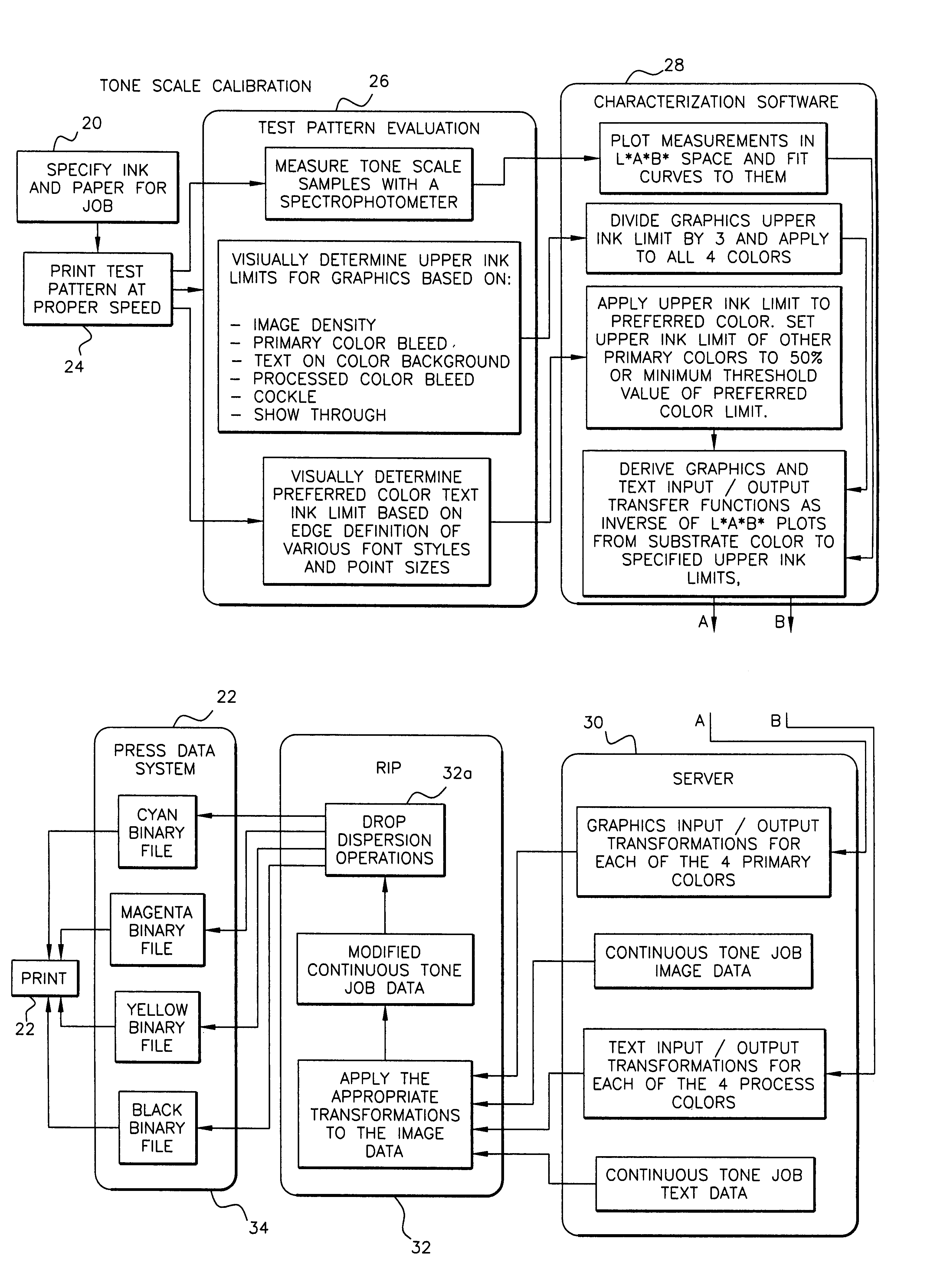
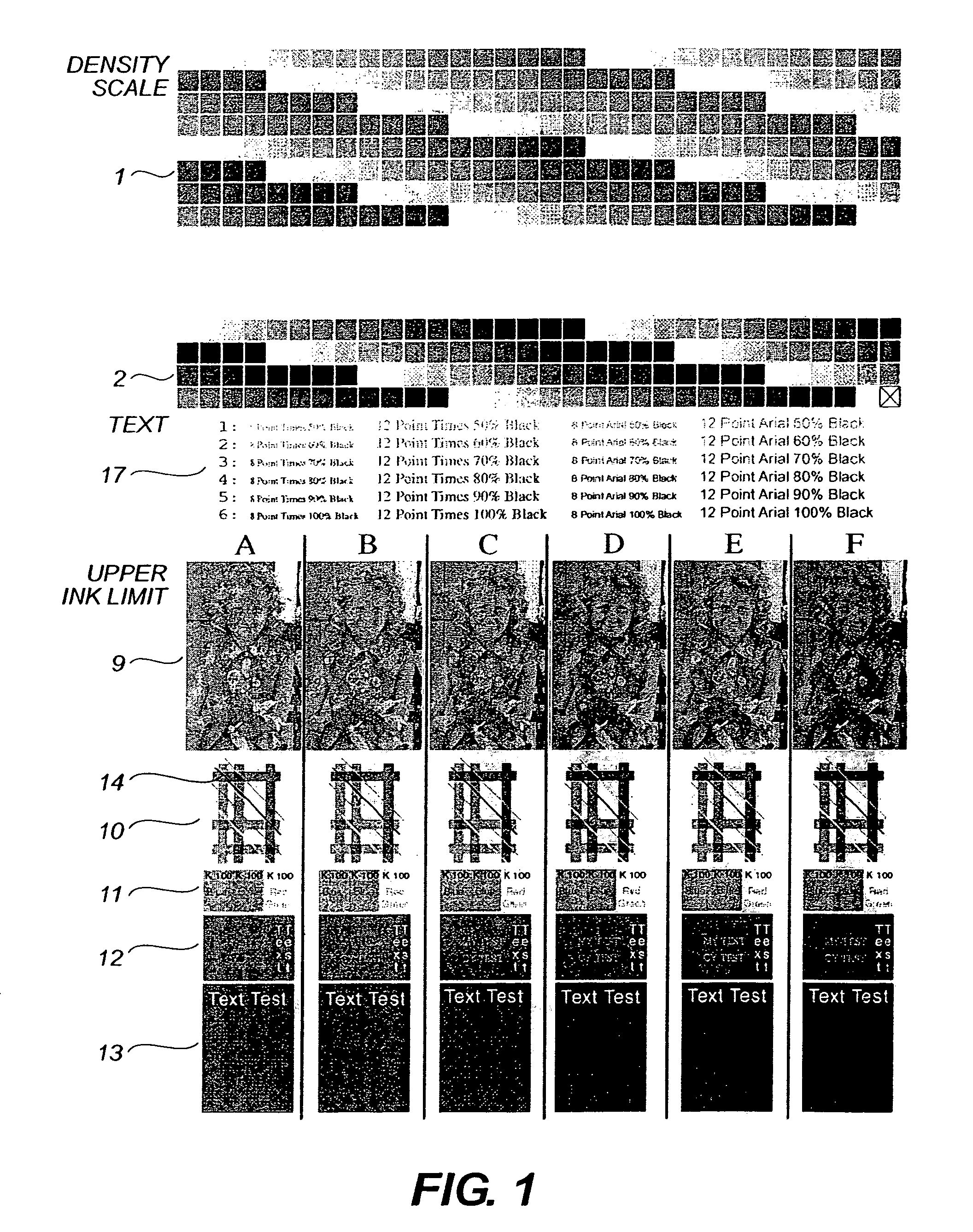
[0015]The present invention optimizes image quality in a printer as a function of the inking system and the substrate accepting the ink. A single page test pattern has been devised that allows one to accomplish this task. This test page is printed on the printer at the same operational conditions as the actual print job to be optimized. The pattern is so constructed to bracket the practical usable range of ink loading on a variety of substrates. In this way, a substrate of unknown characteristics can be quantified through a series of steps that identify the upper ink limit for graphics, the optimum text printing density, and the calibration of the tone scale for each ink in the system based on the color of the unprinted substrate.

[0016]Any suitable test pattern can be selecting, realizing that any number of patterns can be devised to accomplish the objectives of the present invention. This invention discloses the general methods and principles applied to any such test pattern that c...


PUM

PropertyMeasurementUnit
color testaaaaaaaaaa
compatibilityaaaaaaaaaa
color intensityaaaaaaaaaa

Abstract

The present invention addresses the quantification of a printed tone scale for each individual color in a printing system, developing a linear tone scale derived in an independent color space and referenced from the shade of the unprinted substrate. The present invention determines the threshold for excessive ink coverage of a printing system on a specified substrate. This determination is based on a subjective evaluation of acceptable thresholds for bleed, cockle, show through, and image density. The method works in conjunction with a predefined test pattern printed on the specified substrate at fixed printing parameters, such as speed, dryer temperature, and web tension. This invention also includes an ability to limit the ink of each independent color in the system as a fraction of the total upper ink limit. Furthermore, this invention allows calibration of the tone scale of each color in the system using the color of the paper as a reference point. In addition, this invention facilitates the generation of separate sets of tone scale transformations for both graphics and text for each color in the system.

Description

TECHNICAL FIELD[0001]The present invention relates to image processing and, more particularly, to optimizing substrate specific image quality from a printing system.BACKGROUND ART[0002]Ink jet printing systems are known in which a print head defines one or more rows of orifices which receive an electrically conductive recording fluid, such as for instance a water based ink, from a pressurized fluid supply manifold and eject the fluid in rows of parallel streams. Printers using such print heads accomplish graphic reproduction by selectively charging and deflecting the drops in each of the streams and depositing at least some of the drops on a print receiving medium, while others of the drops strike a drop catcher device.[0003]In certain printing systems, particularly ink jet printing systems, the amount of ink or other colorant applied to the substrate must be limited. In the case of high speed ink jet printing systems, using water based dye inks, ink limiting is of particular concer...

Claims


Application Information

Patent Timeline
Patent Type & Authority Patents(United States)
IPC IPC(8): G06F15/00G03F3/08G06K9/00H04N1/407H04N1/60
CPCH04N1/4078H04N1/6097H04N1/6033
Inventor PIATT, MICHAEL J.WOZNIAK, TERRYWATKINS, CHRISTOPHER L.
Owner EASTMAN KODAK CO
Why Eureka
Try Eureka