Floating platform shock simulation system and apparatus

a floating platform and shock simulation technology, applied in the direction of instruments, structural/machine measurement, force measurement by elastic gauge deformation, etc., can solve the problems of increasing the shock energy of the unit, challenging the shock, and decaying waves

Inactive Publication Date: 2006-05-30
THE UNITED STATES OF AMERICA AS REPRESENTED BY THE SECRETARY OF THE NAVY
View PDF4 Cites 16 Cited by
  • Summary
  • Abstract
  • Description
  • Claims
  • Application Information

AI Technical Summary

Problems solved by technology

This Military Specification defines a “heavyweight” test category that mandates shock testing “on a standard or large floating shock platform” that herein is denominated a “test barge.” Acceptable testing for heavyweight shocks is quite challenging, usually requiring actual detonation of explosive devices near a floating barge containing the principle unit equipment.
Some of the most devastating impulses are created by the aftershock concussions (secondary bubble pulses), which result in a decaying wave of compression and rarefaction that transmits even greater shock energy to the unit under test.
The range of shock varies, but can approach 50 g. According to MIL-S-901D, the lighter test categories may be performed in the laboratory by using various shock machines but, to properly test for the effects of secondary bubble pulses, the heavyweight tests must be performed on a test barge subjected to an actual underwater detonation, which is intrinsically hazardous.
These two hammer tests do not properly stress equipment that is resiliently mounted because they provide neither a sufficient platform displacement nor a proper frequency response in the lower end of the shock response spectrum (SRS).
Adding a spring-deck apparatus to the Medium Weight Shock Machine can adjust the SRS but does not achieve sufficient platform displacement.
When the isolators are bottomed-out, the equipment can be subjected to a more severe shock than seen without isolation (i.e., “hard-mounted”).
Such a barge test is considerably more expensive and hazardous and requires more lead time than a land-based laboratory test.
Until now, such a shock wave could not be realistically simulated in the land-based laboratory.
However, Hansen neither considers nor suggests solutions to the MIL-S-901D heavyweight secondary bubble pulse simulation problem.

Method used


Image

  • Floating platform shock simulation system and apparatus
  • Floating platform shock simulation system and apparatus
  • Floating platform shock simulation system and apparatus

Examples


embodiment 20

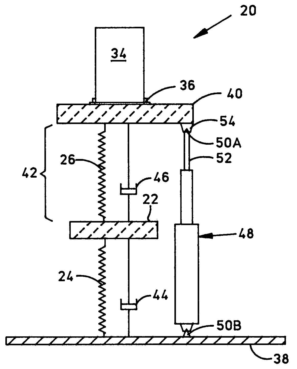
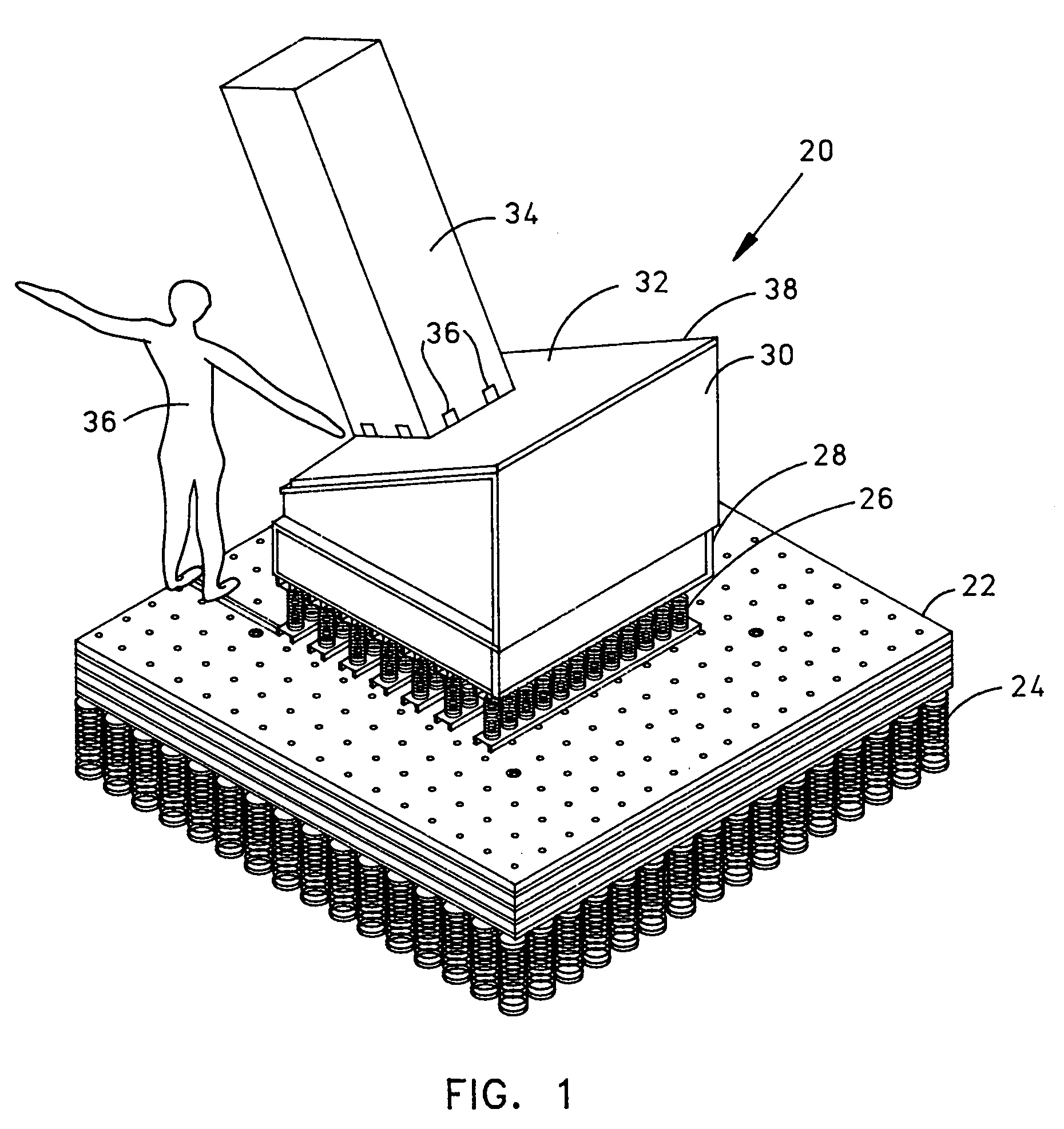
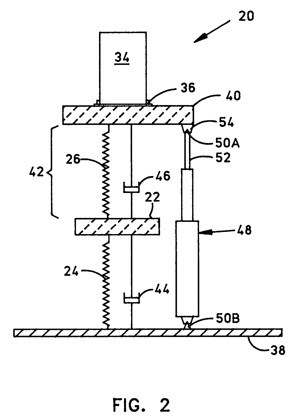
[0026]FIG. 1 shows a perspective diagram of a “two-degree-of-freedom” (2DOF) embodiment 20 of the system of this invention. A first mass element 22 includes, for example, a stack of heavy steel plates fastened together is supported by the first spring element 24, which is coupled between mass 22 and a primary system supporting plane (not shown). Spring 24 includes scores of coil springs operating in parallel in the example shown. The second spring element 26 is coupled between mass 22 and another lighter mass (not separately labeled) that includes a steel assembly 28 coupled to a mounting adapter 30. The mass comprising frame 28 and adapter 30 may be considered to be a single mass element for the purposes of this invention. Adapter 30 provides a 30-degree tilted rigid mounting surface 32 on which the equipment 34 under test is fastened by means of the fasteners 36, for example. The 30-degree mounting angle can be changed to any desired value by replacing adapter 30 and it can be rea...

embodiment 68

[0032]FIG. 5 shows a perspective diagram of a “three-degree-of-freedom” (3DOF) embodiment 68 of the system. It differs from system 20 (FIG. 1) in that the rigid surface 32 is replaced with a flexible plate structure 75 that straddles the two rail surfaces of adapter 30. Flexible plate structure 75 may be considered a mass-spring combination element including mass 70 and a spring 72 (FIG. 6) for the purposes of this discussion.

[0033]FIG. 6 is a schematic diagram illustrating the mechanical elements of system 68 of FIG. 5 and showing some additional elements that are not visible in FIG. 5. System 68 is generally adapted from system 20 (FIG. 2) by adding a third mass-spring system that includes the mass 70 and the spring 72, which spans the separation distance 74 between mass 70 and mass 40. The damping element 76 represents any losses in this third mass-spring system. Note that mass 70 is not drawn down by cocking apparatus 48 so that spring 72 is not available for storing any energy ...


PUM

PropertyMeasurementUnit
massaaaaaaaaaa
storing energyaaaaaaaaaa
energyaaaaaaaaaa

Abstract

A shock simulation system including a support plane, a first mass element and a first spring element attached between the support plane and the first mass element. Also included, is a second mass element that is attached to the first mass element with a second spring element as well as a cocking apparatus, positioned between the support plane and the second mass element, that is capable of accumulating and storing energy in the spring elements. The system also includes a trigger for releasing the energy stored in the springs and for causing a mechanical shock event that is substantially transferred to the second mass.

Description

STATEMENT OF GOVERNMENT INTEREST[0001]The invention described herein may be manufactured and used by or for the Government of the United States of America for Governmental purpose without the payment of any royalties thereon or therefore.FEDERALLY-SPONSORED RESEARCH AND DEVELOPMENT[0002]This application is assigned to the United States Government and is available for licensing for commercial purposes. No license is necessary when used for Governmental purposes. Licensing and technical inquiries should be directed to the Office of Patent Counsel, Space and Naval Warfare Systems Center, San Diego, Code 20012, San Diego, Calif., 92152; telephone (619)553-3001, facsimile (619)553-3821.BACKGROUND OF THE INVENTION[0003]1. Field of the Invention[0004]This invention relates generally to hydrostatic shock simulation systems and more particularly to apparatus for simulating the shock effects on barge-mounted equipment of an underwater weapon detonation.[0005]2. Description of the Related Art[...

Claims


Application Information

Patent Timeline
Patent Type & Authority Patents(United States)
IPC IPC(8): G01L1/04
CPCG01M7/08
Inventor MALTBY, JOHN D.
Owner THE UNITED STATES OF AMERICA AS REPRESENTED BY THE SECRETARY OF THE NAVY
Why Eureka
Try Eureka