
Internal slip connector

Active Publication Date: 2006-05-30
WAVEFRONT TECHNOLOGY SOLUTIONS
View PDF7 Cites 9 Cited by
  • Summary
  • Abstract
  • Description
  • Claims
  • Application Information

AI Technical Summary

Benefits of technology

"The invention is an internal slip connector that can be easily attached and released from the inside wall of a conduit, such as coiled tubing or pipe. It is adjustable to tightly engage the wall and withstand tensile loading even if the wall thickness or inside diameter vary significantly for a given nominal diameter. The connector has a mandrel with a head end, an externally threaded end, a reduced diameter shaft section, and an axial bore. It also has two cooperatively aligned slip segments that are in loose sliding engagement around the mandrel and can slide along an oblique interface where they abut each other and are canted apart slightly in opposite radial directions. The slip segments have gripping surfaces that press into engagement with the inside wall of the conduit. The connector can support the weight of the attached tools or devices and can be easily removed by loosening the threaded collar and nut."

Problems solved by technology

However, the conventional, commercially available slip connectors typically fit only a single wall thickness of tubing or pipe.

Method used


Image

  • Internal slip connector
  • Internal slip connector
  • Internal slip connector

Examples


Embodiment Construction

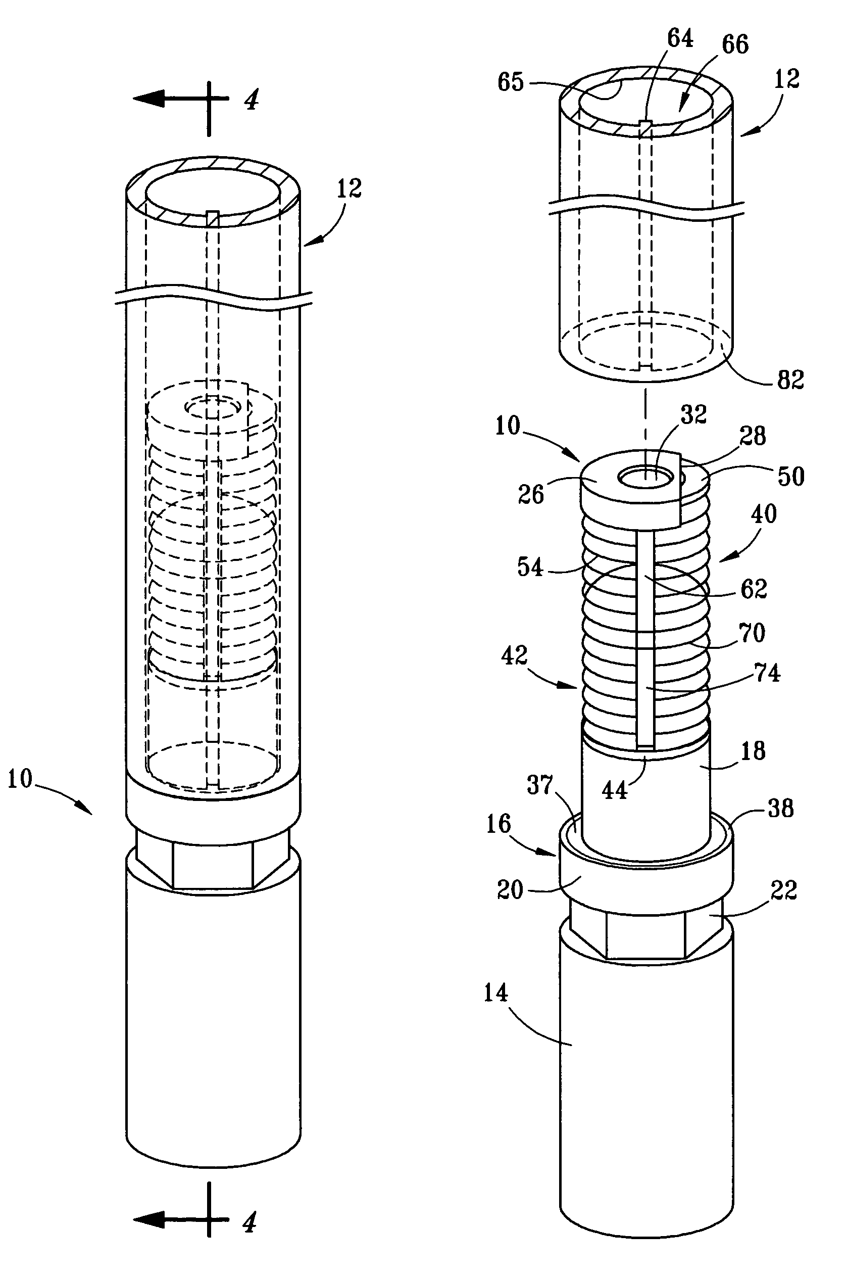
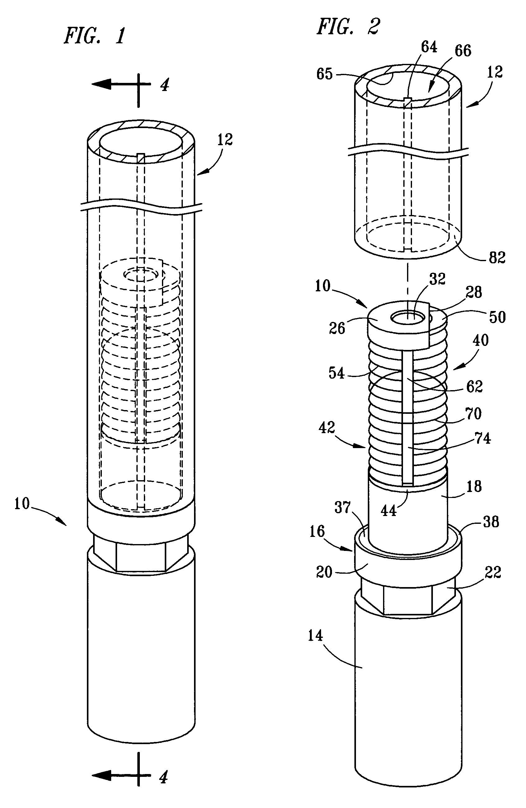
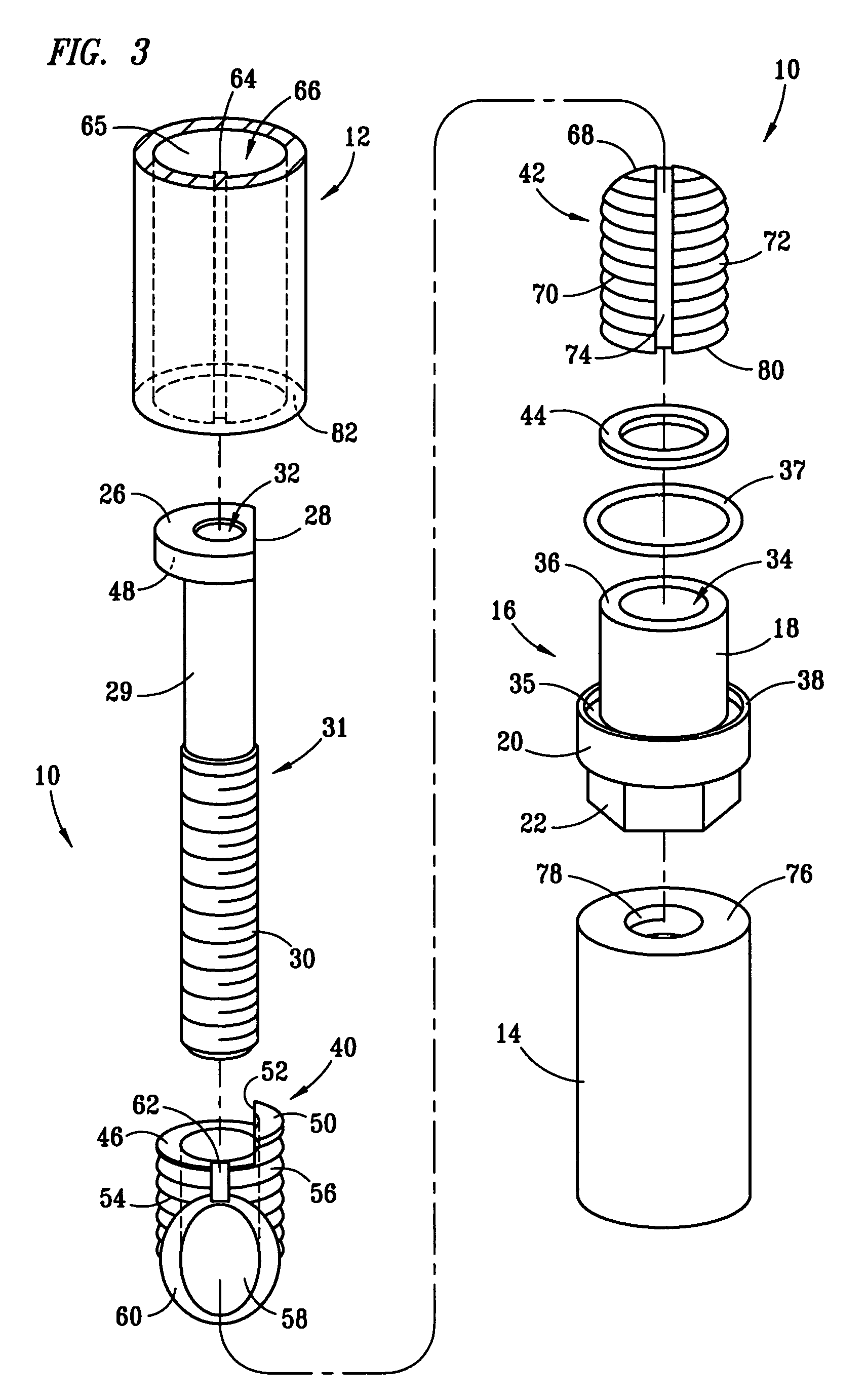
[0020]Referring to FIG. 1, internal slip connector 10 of the invention is shown with its top portion extending upwardly into the substantially cylindrical bore of a segment of coiled tubing 12. Referring to FIGS. 2 and 3, in which coiled tubing segment 12 is exploded away from internal slip connector 10, slip connector 10 further comprises collar 14, threaded nut 16, thrust washer 44, slip segments 40, 42, and mandrel 31 having head 26, shaft 29 with a diameter reduced relative to the maximum transverse dimension of the head, threaded lower end 30 and an axial bore 32. Coiled tubing 12 is generally cylindrical and comprises an inside wall 65 defining an axial bore 66. Seam 64, which is typically created when two edges are welded together during manufacture of the tubing, can project radially inward a small distance relative to the inside diameter of axial bore 66.

[0021]The threaded length of threaded end 30 of mandrel 31 is desirably long enough to allow threaded nut 16 and collar 1...


PUM


Abstract

An internal slip connector useful for attaching tools or other devices to the inside wall of a conduit, the connector having a mandrel with a head end, a threaded end, a reduced-diameter shaft section disposed between the head end and the threaded end, two abutting slip segments loosely disposed around the mandrel between the head end and an upper extending portion of the threaded end, and a nut threaded onto the mandrel below the slip segments. When tightened following insertion of the slip segments into the conduit, the nut causes the slip segments to slide radially outward along an oblique interface between them. Gripping surfaces disposed on the outside of the slip segments are thereby pressed into engagement with the inside wall of the conduit. The internal slip connector can be used with coiled tubing of various wall thicknesses and is easily released after loosening the threaded nut.

Description

BACKGROUND OF THE INVENTION[0001]1. Field of the Invention[0002]This invention relates to apparatus useful for releasably securing one or more devices, especially well tools, to the free end of a conduit such as coiled tubing or pipe prior to running the conduit into a well bore.[0003]2. Description of Related Art[0004]The use of coiled tubing for running tools or other devices into the bore of an oil or gas well is well known. Coiled tubing is made of steel and is typically delivered to a well site on truck-mounted spools or reels and run into a well bore inside production tubing or casing that is already in place. Coiled tubing is made in various nominal diameters ranging, for example, from ¾ to 4½ inches, with nominal diameters of 1¼ inches to 2½ inches being quite common. Because coiled tubing is most often made by roll forming and welding a continuous strip of steel, a raised seam line often extends longitudinally down the inside wall of the tubing. Except for the seam line, th...

Claims


Application Information

Patent Timeline
Patent Type & Authority Patents(United States)
IPC IPC(8): E21B17/02E21B17/04F16L33/213F16L37/12
CPCE21B17/04F16L37/1235F16L33/213Y10T403/76E21B17/041
Inventor DODD, REX A.
Owner WAVEFRONT TECHNOLOGY SOLUTIONS
Learn More