Eureka AIR delivers breakthrough ideas for toughest innovation challenges, trusted by R&D personnel around the world.

Ink assist air knife

Inactive Publication Date: 2006-05-30
HEWLETT PACKARD DEV CO LP
View PDF36 Cites 16 Cited by
  • Summary
  • Abstract
  • Description
  • Claims
  • Application Information

AI Technical Summary

Problems solved by technology

Wet print imaging will smudge, however, if the drying apparatus contacts the print imaging.
The application of heat energy and consequent drying of wet media when in a curved condition, i.e., as wrapped against a roller, often results in undesirable cockling and / or buckling or curvature of output.
As a result, such media often suffers in quality and in some cases requires additional processing to flatten the media.
Generally, application of heat energy to wet ink volatilizes the ink and thereby dries print imaging produced thereby.
Unfortunately, volatizing ink produces ink vapor which may contaminate a printing operation and may inhibit further drying.
Direct contact with print imaging prior to it being suitably dry can result in undesirable smudging and degradation thereof, as was the case in earlier media handling systems, such as those using star-wheels in the media output path.
Ink formulations, drying mechanisms, and printing techniques directed toward improved ink drying time, however, sometimes present undesirable side effects.
Expensive and elaborate ink drying systems, however, are not as easily justified for use in conjunction with expensive fast-dry inks.
Given an investment in fast-dry inks, further investment in elaborate ink drying systems may be partially redundant and, to some extent, can in some cases represent an inefficient use of resources.
As a result, ink drying systems typically are not used in conjunction with printing operations making use of expensive fast-dry inks.

Method used


Image

  • Ink assist air knife
  • Ink assist air knife
  • Ink assist air knife

Examples


Embodiment Construction

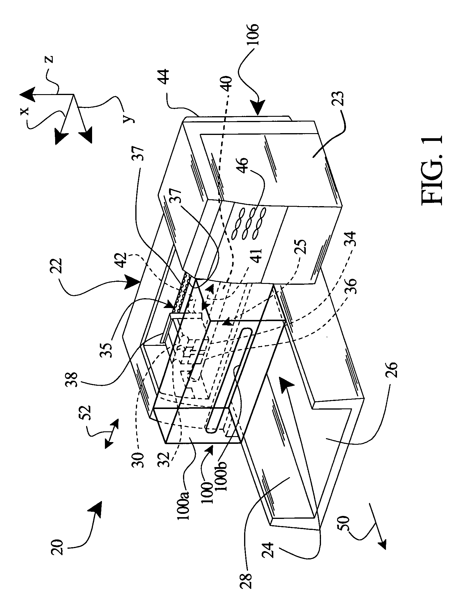
[0022]FIG. 1 illustrates one embodiment of a typical inkjet printing mechanism, specifically an inkjet printer 20. The present invention will be illustrated in the context of or as applied to a typical inkjet printing mechanism, e.g. in the context of or as applied to inkjet printer 20 of FIG. 1. It will be understood, however, that printer components and particular component architectures vary from model to model and that the present invention applies across a variety of inkjet printing mechanism implementations even though not illustrated herein, such as plotters, photo imagers, facsimile machines, copiers, multi-function machines, etc.

[0023]Printer 20 includes a chassis 22 to which various printer components are mounted and then surrounded by a housing or casing 23. Within chassis 22 and casing 23, a print media handling system 24 supplies sheets of media (not shown in FIG. 1) to the printer 20. Media may be of a variety of generally sheet-form materials, such as plain, premium a...


PUM


Abstract

In operating an inkjet printing mechanism, media passes through a printzone including a support apparatus supporting the media thereat. When passing through the printzone, print imaging is applied by application of ink from an ink dispensing element and onto a surface of the media. The method includes directing an airflow at the media surface, the airflow including a first directional component away from the printzone and a second directional component onto the media surface thereby urging the media against the support apparatus.

Description

BACKGROUND OF THE INVENTION[0001]The present invention relates generally to printing methods and apparatus, and can relate in certain aspects to ink drying methods and apparatus as applied in the context of inkjet printing operations.[0002]Inkjet printing produces print imaging by propelling ink droplets onto media. A variety of inkjet printing mechanisms have evolved, but generally share in a common characteristic of rendering an image by depositing liquid ink, e.g., ink formulations including evaporatable components, on a media substrate. As such, inkjet printing methods and operations sometimes include drying of media, e.g., drying liquid ink to remove evaporatable components following application thereof to media. Thus, the “wet” nature of ink as applied to produce print imaging by inkjet printers has lead to the development of ink drying systems.[0003]Inkjet drying techniques include passing media with wet print imaging against or near heated rollers and platens. Wet print imag...

Claims


Application Information

Patent Timeline
IPC IPC(8): B41J2/01B41J11/00
CPCB41J11/002B41J11/0022
Inventor PICKUP, RAY L.
Owner HEWLETT PACKARD DEV CO LP
Why Eureka
Eureka Blog
Learn More