Gear screw adjuster

a screw adjuster and screw technology, applied in the direction of coupling device connection, lighting support device, instruments, etc., can solve the problem of insufficient sealing, and achieve the effect of reducing screw torque variation, easy installation, and cost-effectiveness

Inactive Publication Date: 2006-05-30
BURTON TECH
View PDF35 Cites 19 Cited by
  • Summary
  • Abstract
  • Description
  • Claims
  • Application Information

AI Technical Summary

Benefits of technology

[0007]The present invention provides a gear screw adjuster assembly that is cost-effective, easily installed in the lamp where it is securely retained, provides an improved seal reduces screw torque variation, and which solves the problems raised or not solved by existing designs. In one embodiment, the gear screw directly snap fits into the headlamp housing. In some embodiments, the gear screw is first inserted into an adjuster housing. Then, the screw and adjuster housing are together snap fit into the headlamp housing. In another embodiment, the gear screw is snap fit into the adjuster housing which engages the headlamp housing in the well-known quarter-turn fashion. After the gear screw, and any accompanying adjuster housing, has engaged the headlamp housing, the reflector of the headlamp assembly is positioned to engage the gear screw. The gear screw is threaded so that rotation of the gear screw translates the reflector into the correct position.
[0008]In addition, the gear screw adjuster assembly achieves a substantially improved seal between the headlamp reflector and the headlamp housing while reducing screw torque variation. The present invention achieves a radial compression seal around the O-ring. Such a radial compression seal is accomplished by controlling the diameter of the screw and inner diameter of the housing. The result is less variation in seal compression, reduced screw torque variation, and improved sealing as opposed to the conventional facial seal.
[0009]In one embodiment of the present invention, the gear screw assembly can be securely inserted and retained in the headlamp housing without the additional step of adding a push-on fixer to the screw engagement as is required in certain conventional adjusters. Alternatively, the gear screw may be first snap fit into an adjuster housing which is then inserted and engaged in the headlamp housing in the traditional quarter turn fashion or other manner.

Problems solved by technology

Such variations in facial compression has been found problematic in that it can cause wide variations in screw torque and can result in inadequate sealing.

Method used


Image

  • Gear screw adjuster
  • Gear screw adjuster
  • Gear screw adjuster

Examples


Embodiment Construction

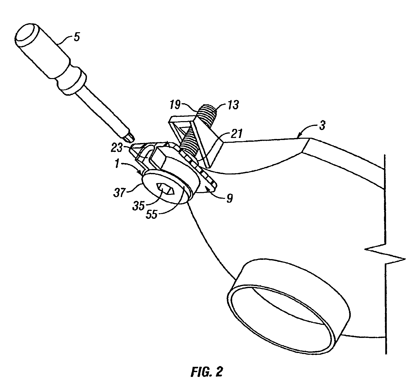
[0030]Three illustrative embodiments of a gear screw adjuster assembly (identified generally as 1) in accordance with the present invention are shown in FIGS. 1 through 17. While the invention may be susceptible to embodiment in different forms, there is shown in the drawings, and herein will be described in detail, certain illustrative embodiments with the understanding that the present disclosure is to be considered an exemplification of the principles of the invention, and is not intended to limit the invention to those as illustrated and described herein. Additionally, features illustrated and described with respect to one embodiment could be used in connection with other embodiments.

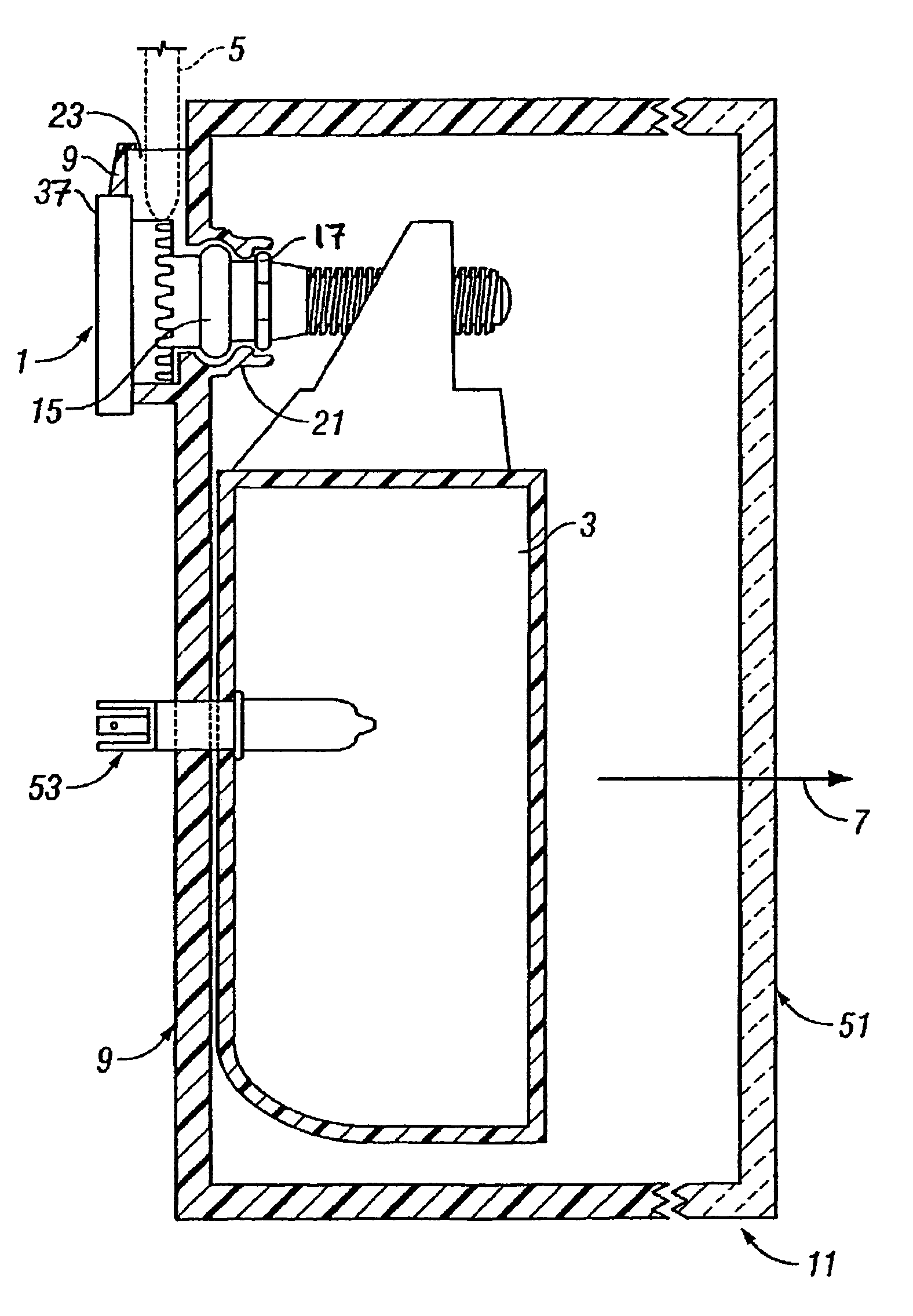
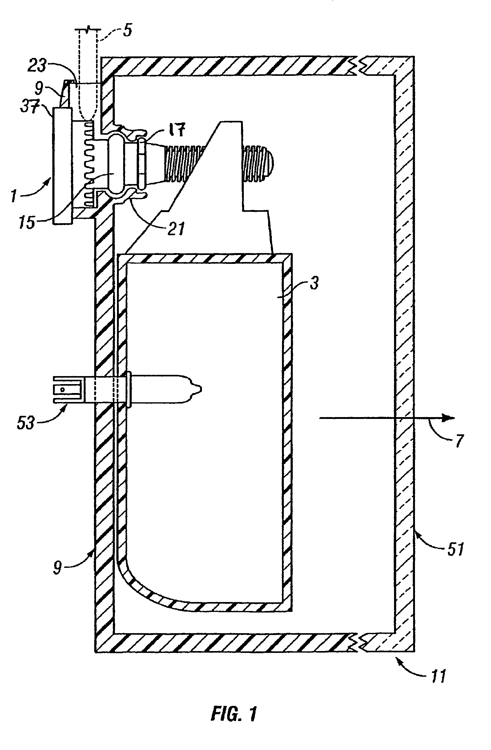
[0031]FIG 1 shows a headlamp assembly 11 whereby the desired aiming of the headlamp as indicated by an arrow 7 is achieved by actuating a gear screw adjuster assembly 1. The headlamp assembly 11 comprises many parts, including but not limited to, a housing 9, a moveable reflector 3, a lens 51, and t...


PUM


Abstract

A headlamp assembly including a simplified adjusting mechanism for adjusting the aim of the headlamp. The mechanism includes a gear screw that is snap fit into the headlamp housing with or without an adjuster housing. The gear screw has an O-ring in radial compression so as to ensure a good seal.

Description

BACKGROUND OF THE INVENTION[0001]This invention relates generally to adjusting devices, and in particular to a gear screw adjuster used in connection with motor vehicle headlamps.[0002]As the design of vehicles, automobile, and light trucks in particular, has evolved, headlights have continually been reconfigured to improve the aerodynamics of the front end of the vehicle. Modern headlights are designed so that their lenses follow the contour of the vehicle to provide an aerodynamically efficient exterior surface. However, adjustment of these headlights must still be performed in order to provide an optimal beam of light and to prevent the aiming of light beams toward oncoming vehicles. Automotive manufacturers' demand for aerodynamically efficient headlight designs has lead to modular designs requiring the headlight adjustment mechanism to be located within the interior of the engine compartment so that adjustment can be easily performed without removing any exterior trim pieces. T...

Claims


Application Information

Patent Timeline
Patent Type & Authority Patents(United States)
IPC IPC(8): B60Q1/00B60Q1/26B60Q1/32B60Q11/00B60Q3/00B60Q1/068
CPCB60Q1/0683
Inventor BURTON, JOHN
Owner BURTON TECH
Why Eureka
Try Eureka