Heat-dissipating device and housing thereof

a technology of axialflow fan and heat dissipation device, which is applied in the direction of machines/engines, liquid fuel engines, light and heating apparatus, etc., can solve the problems of high heat generation of electrical devices in operation, easy damage, turbulent airflow, etc., and achieve the effect of largely increasing the static pressure of the fan

Active Publication Date: 2006-05-30
DELTA ELECTRONICS INC
View PDF12 Cites 38 Cited by
  • Summary
  • Abstract
  • Description
  • Claims
  • Application Information

AI Technical Summary

Benefits of technology

[0008]In view of this, the invention provides a heat-dissipating fan and a housing thereof. Stator blades are provided in the housing of the invention, and the ar

Problems solved by technology

In a normal electronic product such as a computer, electronic devices therein generate a lot of heat during operation.
If the electronic devices are cont

Method used


Image

  • Heat-dissipating device and housing thereof
  • Heat-dissipating device and housing thereof
  • Heat-dissipating device and housing thereof

Examples


Embodiment Construction

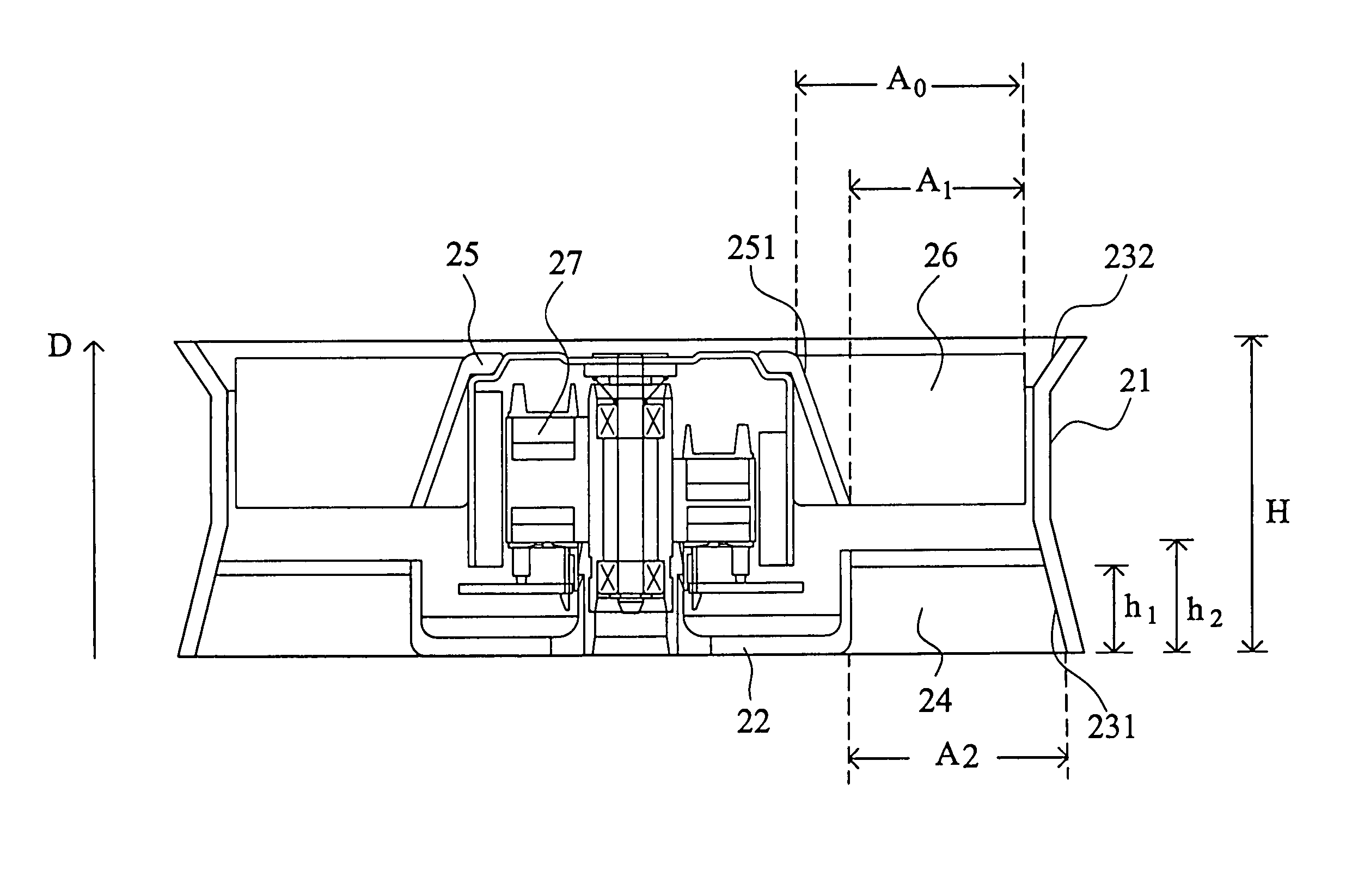
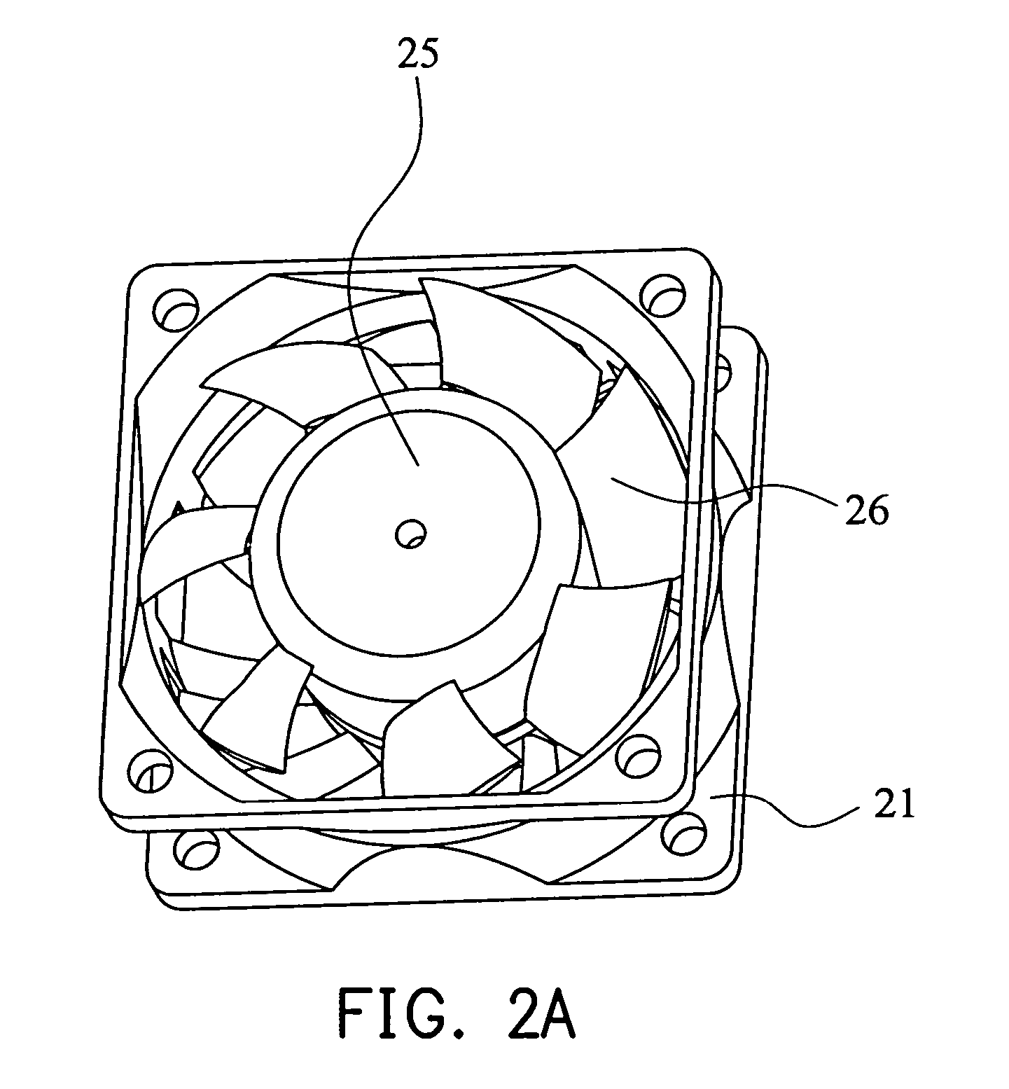
[0027]Referring to FIG. 2A and FIG. 2B, a heat-dissipating fan as disclosed in a first preferred embodiment of the invention is shown. The heat-dissipating fan includes an impeller, a motor 27, and a housing. The impeller includes a hub 25 and a plurality of rotor blades 26 disposed around the hub 25. The motor 27 is disposed in the hub 25 Referring to FIGS. 3A–3C, the housing receives the impeller, and includes an outer frame 21, a base 22, an air-guiding part (or referred to as a lead angle) 231, and a plurality of stator blades 24. The stator blades 24 are connected between the base 22 and the air-guiding part 23 in the outer frame 21. That is, the stator blades 24 are radially arranged and connected between the base 22 and an inner surface of the outer frame 21. The stator blades 24 can guide an airflow through the blades, and increase the static pressure of the airflow discharged from the heat-dissipating fan. Additionally, one end of each of the stator blades 24 may be connect...


PUM


Abstract

A heat-dissipating device and a housing thereof. The heat-dissipating device includes an impeller and a housing. The impeller includes a hub and a plurality of rotor blades disposed around the hub. The housing includes an outer frame, an air-guiding part, and a plurality of stator blades. The air-guiding part is formed on at least one side of the outer frame. The stator blades are disposed in the outer frame corresponding to the air-guiding part. The stator blades guide the airflow through the blades, and greatly increase the static pressure of the airflow discharged from the heat-dissipating device.

Description

[0001]This Nonprovisional application claims priority under 35 U.S.C. §119 (a) on Patent Application No. 092114644 filed in TAIWAN on May 30, 2003, the entire contents of which are hereby incorporated by reference.BACKGROUND OF THE INVENTION[0002]1. Field of the Invention[0003]The invention relates to a heat-dissipating device and a housing thereof, and in particular, the invention relates to an axial-flow fan and a housing thereof.[0004]2. Description of the Related Art[0005]In a normal electronic product such as a computer, electronic devices therein generate a lot of heat during operation. If the electronic devices are continuously operated at high temperature, they are easily damaged. Thus, to prevent damage, a heat-dissipating fan is normally disposed in the electronic product to dissipate heat therein to the surrounding.[0006]The conventional heat-dissipating fan for the computer mainly includes a housing 11 and an impeller 12 with a plurality of blades. As shown in FIG. 1A an...

Claims


Application Information

Patent Timeline
IPC IPC(8): F04D29/54F04D29/00F04D19/00F04D29/52H01L23/467H05K7/20
CPCF04D19/002F04D29/542H01L23/467H05K7/20172H01L2924/0002H01L2924/00
Inventor CHANG, SHUN-CHENLIN, KUO-CHENGHUANG, WEN-SHI
Owner DELTA ELECTRONICS INC
Why Eureka
Try Eureka