Compact traveling-use power adapter structure

a power adapter and compact technology, applied in the direction of flexible/turnable line connectors, connection contact materials, coupling device connections, etc., can solve the problems of inconvenient portability or difficulty in adjusting the power adapter, and achieve the effect of facilitating portability, simple operation, and minimizing the volume of the entire devi

Inactive Publication Date: 2006-05-30
CHENG SHENG HSIUNG
View PDF5 Cites 42 Cited by
  • Summary
  • Abstract
  • Description
  • Claims
  • Application Information

AI Technical Summary

Benefits of technology

[0006]The primary object of the present invention is to provide a small and easy to carry compact traveling-use power adapter structure, having a variety of adapting styles for adjusting, and with practicability and convenience.
[0008]Accordingly, in using the aforementioned structure, a power plug of an electronic product is directly inserted into the slots at the top of the power adapter, and the position of adjustable adapting plugs is adjusted to be in compliance with the type of power socket used in a country. Thus, the room needed for storing two adjustable adapting plugs can be minimized, and a storage method which rotates the adjustable plugs towards the central common grounding terminator is taken, in order to assemble the socket port and the plug port into the same casing, thereby minimizing the entire volume used by the power adapter, and facilitating the easiness of carry. On the other hand, using a rotating method to take out the necessary adjustable adapting plugs, and choosing to retrieve or not to retrieve the central common grounding terminator with the same method as the adjustable adapting plugs, is very simple to operate. In addition, the flat contact terminators and the cylindrical contact terminators also contain adjusting structures, and thus can be used for a variety of power sockets. Accordingly, the present invention is very practical and easy to use.

Problems solved by technology

However, due to large volume of a power adapter, it is inconvenient to carry or difficult to adjust the power adapter.

Method used


Image

  • Compact traveling-use power adapter structure
  • Compact traveling-use power adapter structure
  • Compact traveling-use power adapter structure

Examples


Embodiment Construction

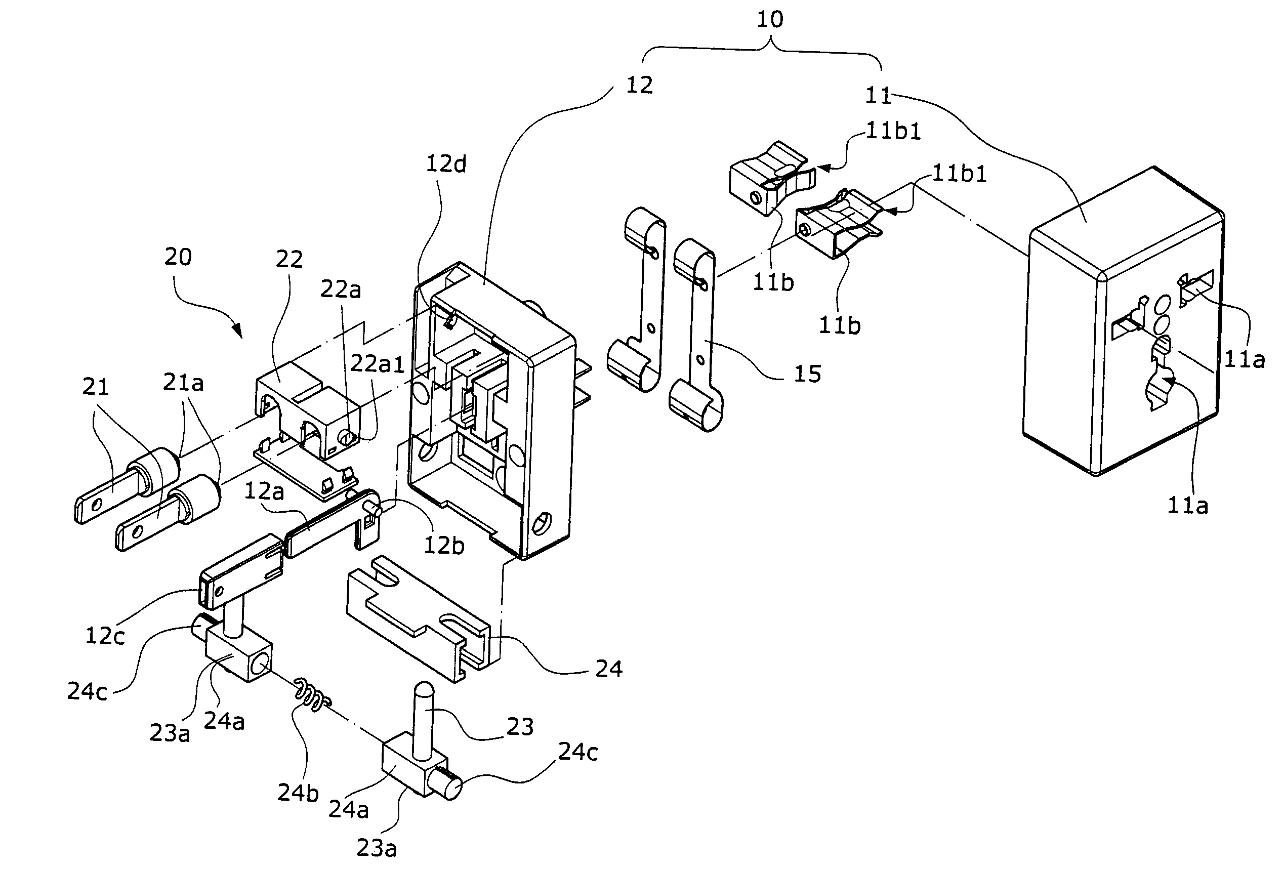
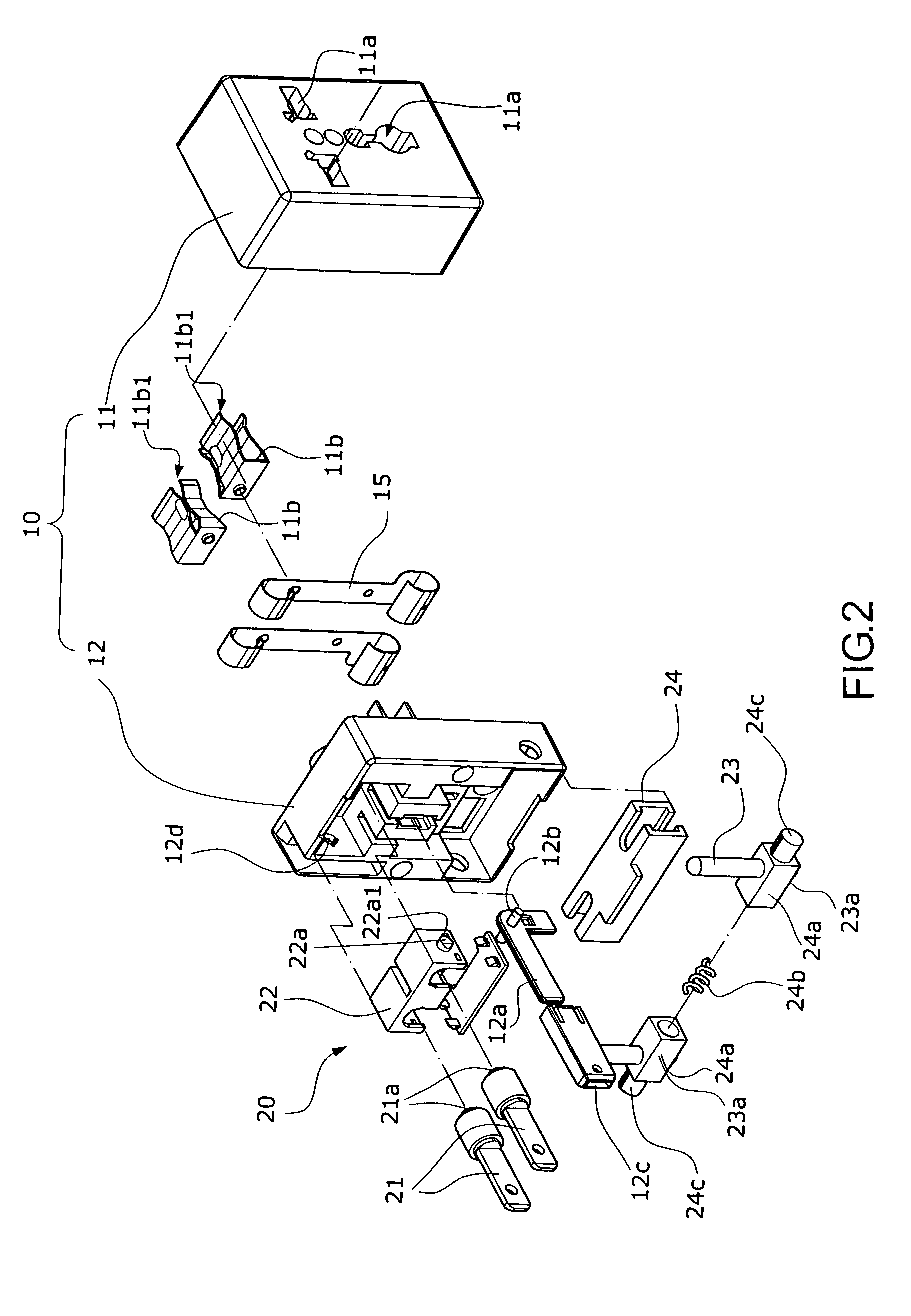
[0023]Referring to FIG. 2, FIG. 3, FIG. 4A, FIG. 4B, and FIG. 4C, the present invention comprises primarily a casing 10, and several adjustable adapting plugs 20, wherein the box-shaped casing 10 is assembled with a top casing 11 and a lower casing 12. Several slots of different types 11a are located at the top of upper casing 11, with corresponding conducting clips 11b inside the slots 11a, which will be aligned with clip parts 11b1 of the conducting clips 11b. The conducting clips are connected with curve-shaped conductible metal plates 15 between the upper casing 11 and lower casing 12, and the conducting clips 11b can clip in a power plug 2 of an electronic product inserted into the slots 11a. Two adjustable adapting plugs 20 are installed on two sides at the bottom of lower casing 12, respectively, with a common grounding terminator 12a installed in the center of the adjustable adapting plugs 20. A pivoting cylinder 12b protrudes from the corner of the L-shaped grounding termin...


PUM


Abstract

A compact traveling-use power adapter structure comprises primarily a casing and several adjustable adapting plugs. The adjustable adapting plugs are installed on two sides at the bottom of the lower casing, and rotate toward a common grounding terminator in the center of the adjustable adapting plugs, thereby achieving the object of storage or opening for use. The two adjustable adapting plugs contain adjustable contact terminators, respectively. In using the aforementioned structure, a power plug of an electronic product is directly inserted into the power adapter, after rotating and opening the adjustable adapting plugs at the bottom of the casing, and adjusting the position or angle of their contact terminators, thereby improving the practicability and convenience.

Description

BACKGROUND OF THE INVENTION[0001]a) Field of the Invention[0002]The present invention relates to a compact traveling-use power adapter structure, and more particularly to a compact traveling-use power adapter, with a small volume and rotational design, that can be widely applied in a variety of power plugs in many countries, for all kinds of electronic products.[0003]b) Description of the Prior Art[0004]In reflecting to a variety of power voltages and currents in countries all of the world, typical house-used electronic products have different power plugs and sockets to be in compliance with their own power voltages and currents. However, there are quite a few of power sockets with similar power voltages and currents. Therefore, in order to be able to use the house-used electronic products in different countries during traveling, a power adapter appears in a market. Referring to FIG. 1, it shows a power adapter a comprising a power plug a2 and a power socket a3 on a casing a1, using...

Claims


Application Information

Patent Timeline
Patent Type & Authority Patents(United States)
IPC IPC(8): H01R29/00
CPCH01R13/6675H01R35/04H01R31/065H01R27/00
Inventor CHENG, SHENG-HSIUNG
Owner CHENG SHENG HSIUNG
Why Eureka
Try Eureka