Locking clamp assembly

a technology of locking clamp and clamp assembly, which is applied in the direction of screws, threaded fasteners, bolts, etc., can solve the problems of unintentional loosen hazardous condition, over-tightening, etc., and achieves the effect of preventing unintentional loosening, allowing tightening of the locking clamp assembly, and positive lock

Inactive Publication Date: 2006-05-30
CABAY JEFFREY J +1
View PDF23 Cites 21 Cited by
  • Summary
  • Abstract
  • Description
  • Claims
  • Application Information

AI Technical Summary

Benefits of technology

[0007]One advantage of the present invention is a positive lock for a locking clamp assembly that prevents unintentionally loosening of the locking clamp assembly.
[0008]Another advantage of the present invention is to simultaneously permit tightening of the locking clamp assembly and prevent loosening of the clamp assembly.
[0009]Yet another advantage of the present invention is to provide a jumper locking clamp assembly that is easy to operate, install and remove.
[0010]A further advantage of the present invention is to provide a jumper locking clamp assembly that does not require new or additional tools for installation and removal.
[0011]An additional advantage of the present invention is to provide a jumper locking clamp assembly that provides a consistent and secure electrical connection or contact.
[0012]Additional advantages and novel features will be set forth in part in the description which follows, and in part will become apparent to those of ordinary skill in the art upon examination of the accompanying drawings or may be learned by production, operation or practice of the invention. The following drawings and description set forth additional advantages and benefits of the invention.

Problems solved by technology

During normal operation, existing jumper locking clamp designs typically encounter unintentional loosening of the locking clamp due to thermal cycling, mechanical vibration or other physical shocks on the conductor experienced during normal use.
The loosening can result in a hazardous condition due to poor electrical connections between the loosened jumper locking clamp and the conductor.
However, over-tightening can deform or damage the current carrying conductor, electrical insulation, or tubular housings.
Also, over-tightening can cause the jumper locking clamp to stick or seize, requiring the use of special tools to assist in the subsequent removal of the jumper locking clamp which leads to increased removal time.
Further, although over-tightening remedies unintentional loosening problems in the short term, unintentional loosening still occurs in the long term which results in hazardous or unsafe conditions, e.g., at installations or facilities that have long intervals between servicing and maintenance.
Thus, re-tightening or over-tightening does not adequately address problems of unintentional loosening of existing jumper locking clamp designs, it only delays the onset of unintentional loosening of the jumper locking clamp.

Method used


Image

  • Locking clamp assembly
  • Locking clamp assembly
  • Locking clamp assembly

Examples


Embodiment Construction

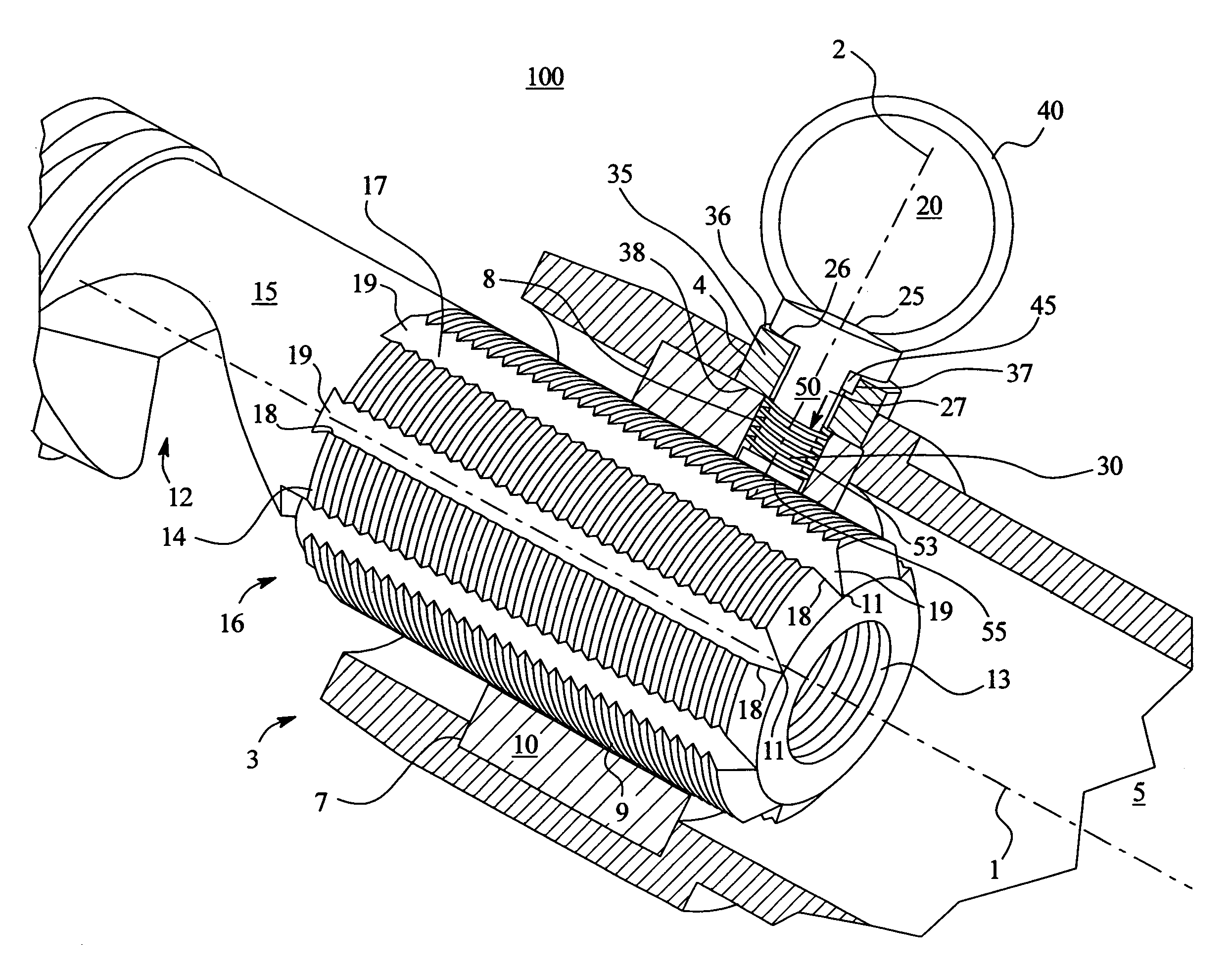
[0023]There is provided a locking clamp assembly that, when engaged or locked, permits movement in only one direction, such as a tightening direction, and prevents movement in a second direction, such as a loosening direction. The locking clamp assembly eliminates and prevents unintentional loosening of the locking clamp assembly due to vibrations, thermal cycling or physical shock encountered during normal operation of the locking clamp assembly.

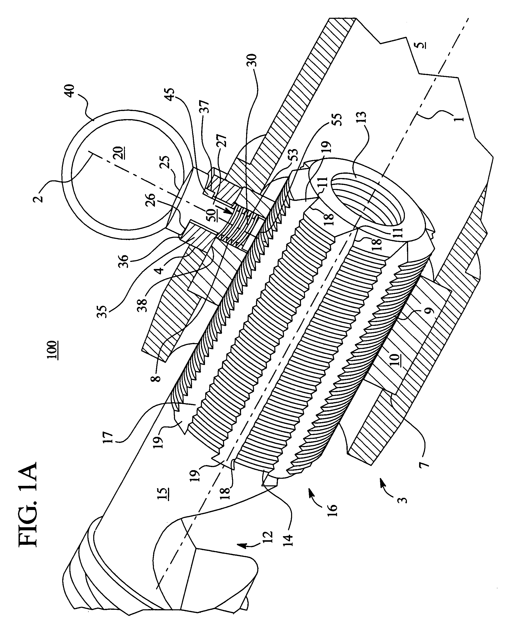
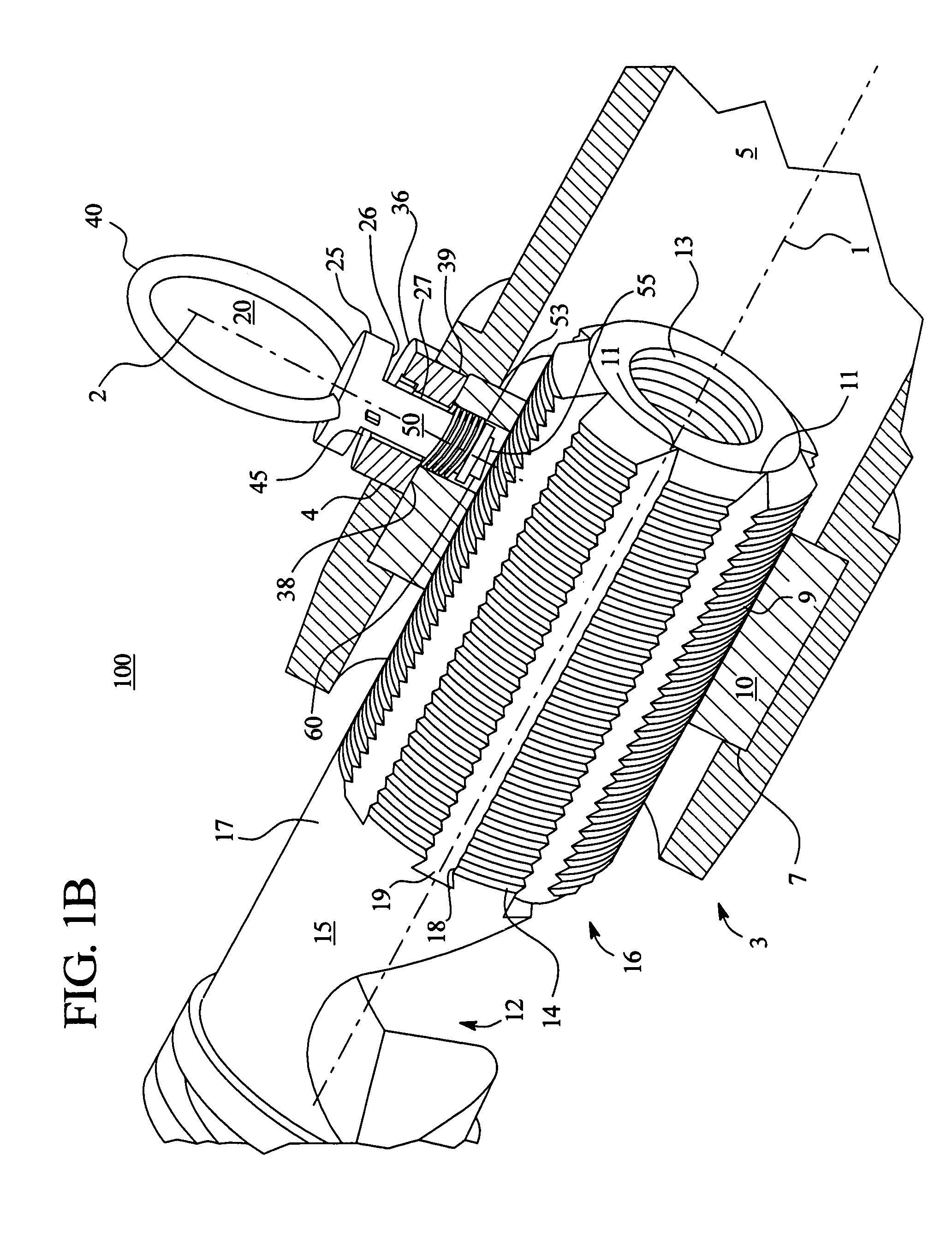
[0024]FIG. 1A shows an isometric view of one embodiment of the locking clamp assembly 100 of the present invention in an engaged or locked position. FIG. 1B shows an isometric view of the locking clamp assembly 100 in a disengaged or unlocked position. The locking clamp assembly 100 includes a clamp body or housing 5 with a threaded insert 10 that preferably screws or threads onto a clamp head 15 having at least one retaining slot 17, and a spring loaded locking mechanism 20 mounted on the clamp housing 5. The clamp head 15 together with th...


PUM


Abstract

A locking clamp assembly that permits movement in one direction and prevents movement in a second direction to eliminate unintentional locking clamp assembly loosening encountered during normal operation. The locking clamp assembly includes a clamp head with a threaded portion and at least one retaining slot traversing the threaded portion, a clamp housing adapted to threadedly received the clamp head, and a locking pin that is operatively mounted on the clamp housing and is positioned adjacent to the retaining slot. When the locking clamp assembly is engaged, the locking pin is adapted to interact with at least one retaining slot to prevent the locking clamp assembly from movement in a first direction and for actuation by a retaining slot to enable movement of the locking clamp assembly in a second direction. There is also an engage means for the locking pin to selectively engaged or disengaged the locking clamp assembly.

Description

TECHNICAL FIELD[0001]The present invention relates generally to clamp locking mechanisms, and particularly to jumper clamp locking mechanisms used in electric current carrying apparatus for attaching a jumper cable to an overhead conductor.BACKGROUND[0002]Jumper clamps and jumper locking clamps for securing current carrying jumper cables to conductors are well known. Existing jumper locking clamps typically comprise a tubular housing having a threaded portion into which a threaded jumper head is screwed. The tubular housing may be a hollow cylindrical tube or body with an internal recessed area that securely accepts a threaded insert which defines a threaded orifice or aperture. The jumper head typically has an upper curved portion that conforms to the shape of a conductor and a lower threaded portion. The jumper head rests on the conductor while the threaded jumper head is threadedly received by the threaded portion of the tubular housing during installation. The threaded jumper he...

Claims


Application Information

Patent Timeline
Patent Type & Authority Patents(United States)
IPC IPC(8): H01R4/30
CPCH01R11/15F16B39/04F16B35/041
Inventor CABAY, JEFFREY J.JACOBAZZI, RALPH J.
Owner CABAY JEFFREY J
Why Eureka
Try Eureka