Lat pulldown weight training machine

a weight training machine and pull-up technology, applied in the field of weight training equipment, can solve the problems of increasing difficulty in movement and intensifying exercis

Inactive Publication Date: 2006-05-30
NAUTILUS INC
View PDF21 Cites 73 Cited by
  • Summary
  • Abstract
  • Description
  • Claims
  • Application Information

AI Technical Summary

Benefits of technology

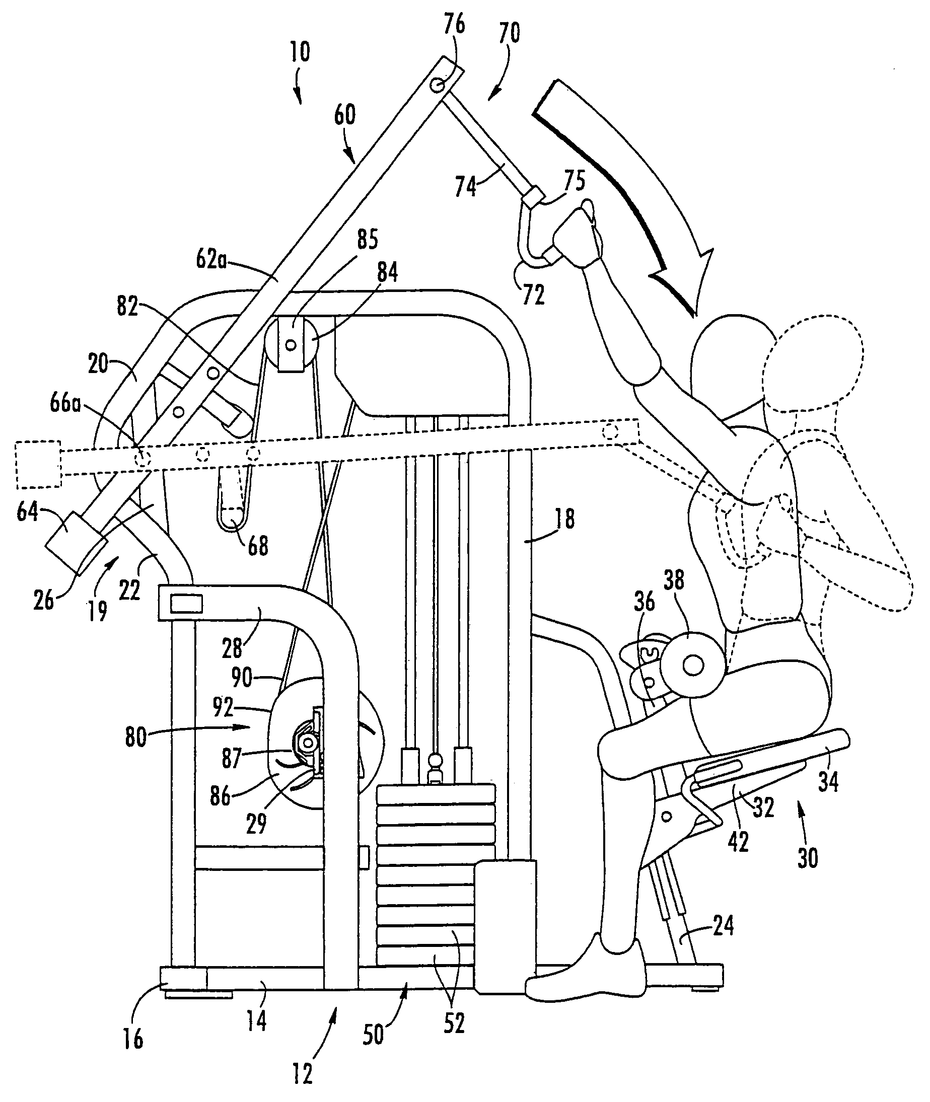
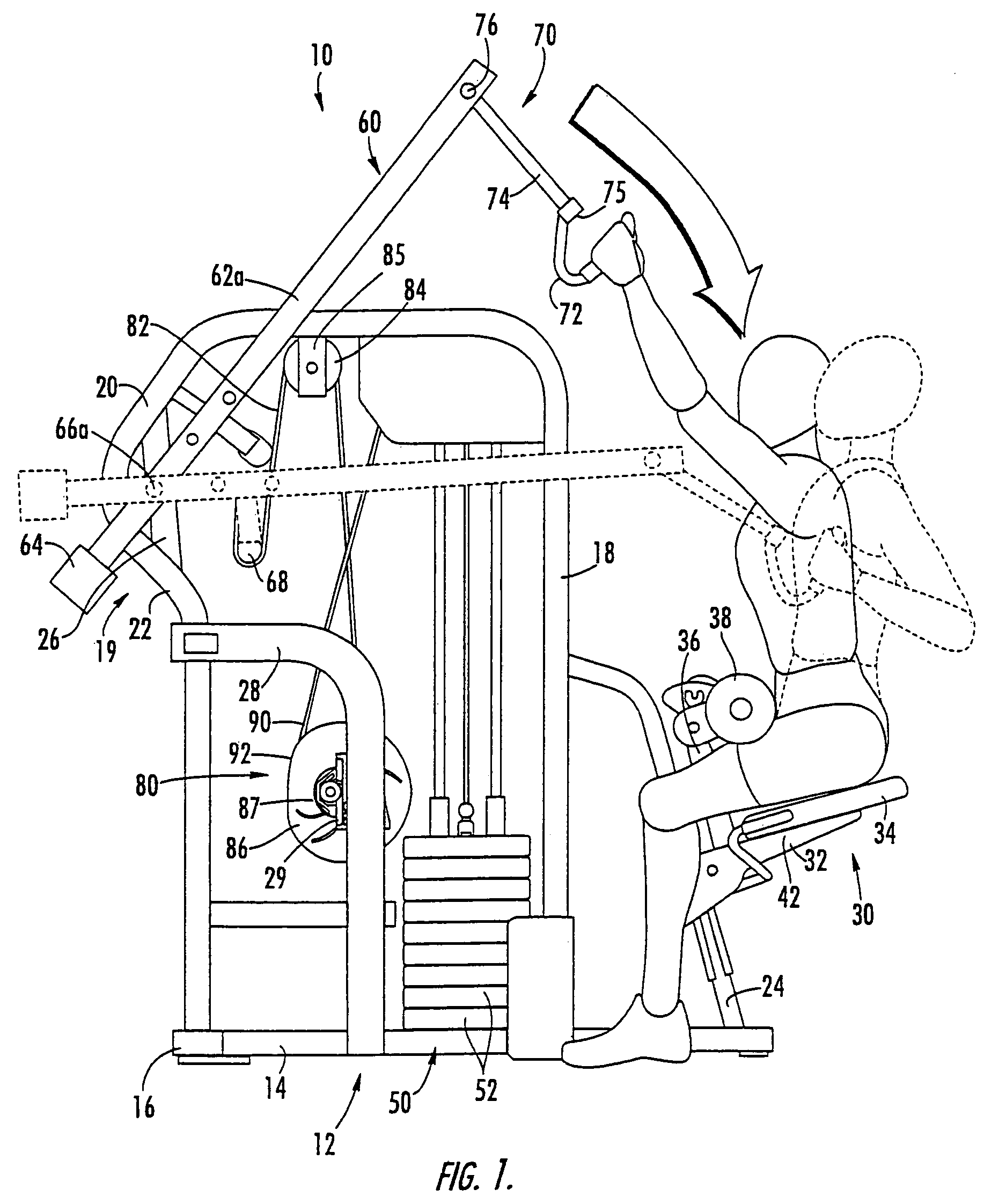
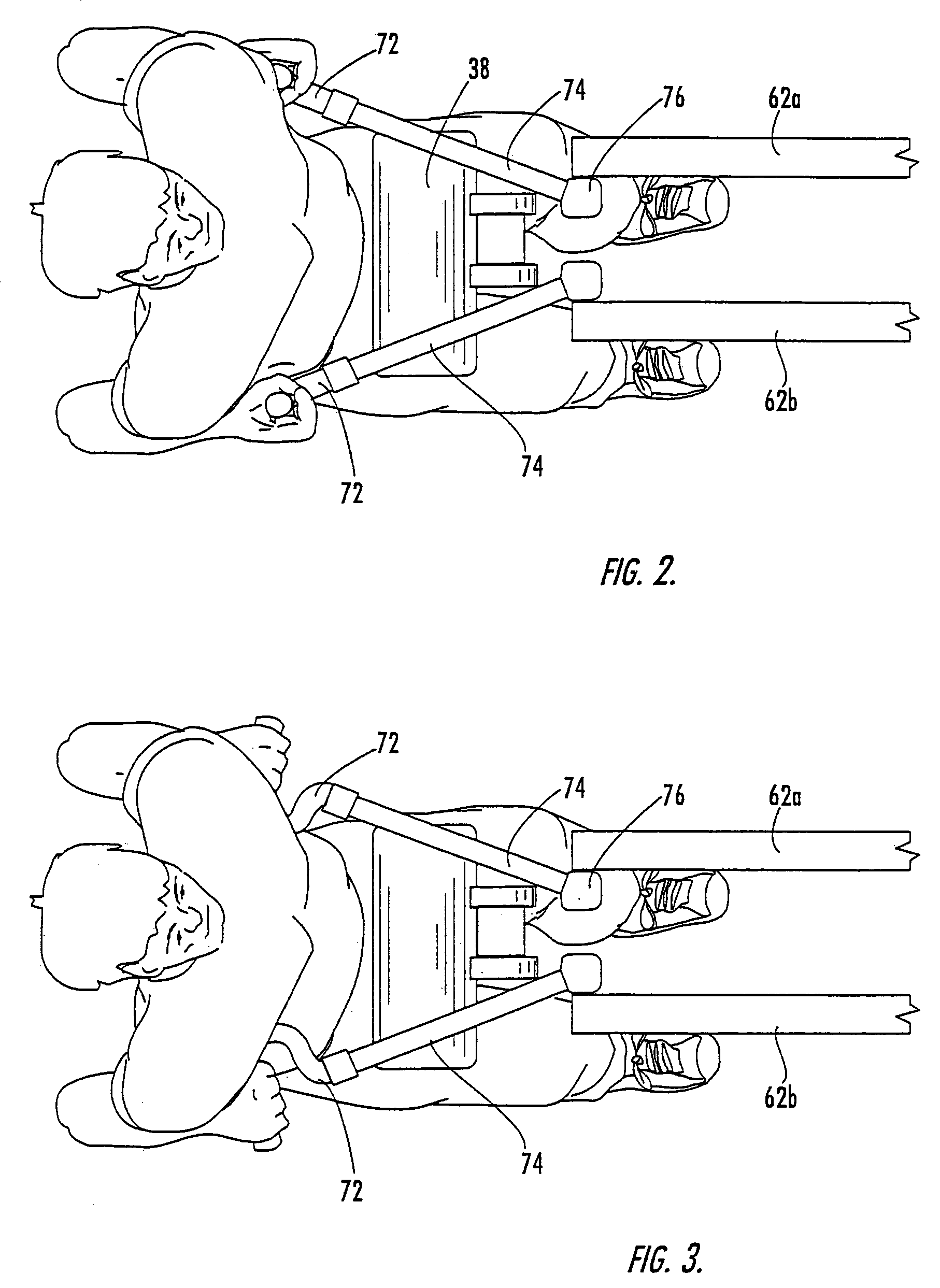
[0008]The present invention can provide a lat pulldown machine that has the capability of enabling the exerciser to employ multiple hand positions and multiple vertical planes of movement. In some embodiments, the inventive exercise machine, which can exercise many of the back muscles of an exerciser, comprises: a frame; a seat assembly attached to the frame; a movement arm pivotally attached to the frame and movable along a stroke path between an upper forward position and a lower rearward position; a resistance-imparting unit operatively connected with the movement arm to provide resistance to the movement arm as it moves from the forward position to the rearward position; a pair of handles to be grasped by the exerciser; and a pair of extension members, each of which is attached to a respective handle such that each handle is free to rotate about a longitudinal axis of the extension member. The extension members are attached to the movement arm such that each extension member is free to at least partially rotate relative to the movement arm about vertical, longitudinal and transverse axes. Also, the extension members are of sufficient length and the extension members are attached to the movement arm (preferably via universal ball joints) so that the handles can be separated by a distance of at least 24 inches when the movement arm is in the rearward position. In this configuration, the exerciser has the option of performing the basic lat pulldown motion with the hands in any orientation, and can pull the handles along multiple vertical planes to multiple positions in front of the chest and shoulders or outside the chest and shoulders.
[0009]In other embodiments of the present invention, an exercise machine comprises: a frame; a seat assembly attached to the frame; a movement arm pivotally attached to the frame and movable along a stroke path between an upper forward position and a lower rearward position; a resistance-imparting unit operatively connected with the movement arm to provide resistance to the movement arm as it moves from the forward position to the rearward position; a pair of handles to be grasped by the exerciser; and a pair of extension members, each of which is attached to a respective handle such that each handle is free to rotate about a longitudinal axis of the extension member. The extension members are attached to the movement arm such that each extension member is free to at least partially rotate relative to the movement arm about vertical, longitudinal and transverse axes. Also, the distance between the attachment of each extension member with the movement arm and the attachment of each extension member with its respective handle is between about 8 and 48 inches. This configuration can provide the same benefits to the exerciser mentioned above.

Problems solved by technology

Conventionally, movement of the mechanical member is resisted in some fashion (often by weights) to render the movement more difficult and thereby intensify the exercise.
This type of machine typically has only a single path of motion available for exercise, and is often limited to a single orientation of the hands during grasping.

Method used


Image

  • Lat pulldown weight training machine
  • Lat pulldown weight training machine
  • Lat pulldown weight training machine

Examples


Embodiment Construction

[0020]The present invention will now be described more fully hereinafter, in which preferred embodiments of the invention are shown. This invention may, however, be embodied in different forms and should not be construed as limited to the embodiments set forth herein. Rather, these embodiments are provided so that this disclosure will be thorough and complete, and will fully convey the scope of the invention to those skilled in the art. In the drawings, like numbers refer to like elements throughout. Thicknesses and dimensions of some components may be exaggerated for clarity.

[0021]Referring now to the drawings, an exercise machine, designated broadly at 10, is illustrated in FIGS. 1–9. The exercise machine 10 includes a frame 12, a seat assembly 30, a weight stack 50, a handle assembly 70, and a belt system 80. These components are described in more detail below.

[0022]In describing the lat pulldown machine 10, it will be assumed for the purposes of description that the terms “front...


PUM


Abstract

An exercise machine for exercising muscles in the back of an exerciser, includes: a frame; a seat assembly attached to the frame; a movement arm pivotally attached to the frame and movable along a stroke path between an upper forward position and a lower rearward position; a resistance-imparting unit operatively connected with the movement arm to provide resistance to the movement arm as it moves from the forward position to the rearward position; a pair of handles to be grasped by the exerciser; and a pair of extension members, each of which is attached to a respective handle such that each handle is free to rotate about a longitudinal axis of the extension member. The extension members are attached to the movement arm such that each extension member is free to at least partially rotate relative to the movement arm about vertical, longitudinal and transverse axes. Also, the extension members are of sufficient length and the extension members are attached to the movement arm (preferably via universal ball joints) so that the handles can be separated by a distance of at least 24 inches when the movement arm is in the rearward position. In this configuration, the exerciser has the option of performing the basic lat pulldown motion with the hands in any orientation, and can pull the handles to multiple positions in front of the chest and shoulders or outside the chest and shoulders.

Description

RELATED APPLICATIONS[0001]This application is a continuation of U.S. patent application Ser. No. 09 / 886,786, filed Jun. 21, 2001 now U.S. Pat. No. 6,746,378, which claims priority from U.S. Provisional Patent Application No. 60 / 296,775, filed Jun. 8, 2001.FIELD OF THE INVENTION[0002]The present invention relates generally to exercise equipment, and relates more particularly to weight training equipment.BACKGROUND OF THE INVENTION[0003]Exercise devices, and in particular weight training machines, typically include a mechanical member that the user repeatedly moves along a prescribed path for exercise. Conventionally, movement of the mechanical member is resisted in some fashion (often by weights) to render the movement more difficult and thereby intensify the exercise. The movement of the mechanical member determines what muscle or muscle groups are to be involved in the exercise.[0004]One popular exercise movement for weight training is the “pull-down” motion, in which a seated exer...

Claims


Application Information

Patent Timeline
Patent Type & Authority Patents(United States)
IPC IPC(8): A63B21/062A63B23/02A63B21/00A63B23/12
CPCA63B21/062A63B21/1469A63B21/1492A63B21/1496A63B21/155A63B21/159A63B23/12A63B21/154A63B2208/0233A63B23/03525A63B23/03533A63B23/1209A63B23/1263A63B21/0628A63B21/4035A63B21/4047A63B21/4049
Inventor MORRIS, MICHAEL WAYNEWEBB, GREGORY M.
Owner NAUTILUS INC
Why Eureka
Try Eureka