This helps you quickly interpret patents by identifying the three key elements:
Problems solved by technology
Method used
Benefits of technology
Benefits of technology
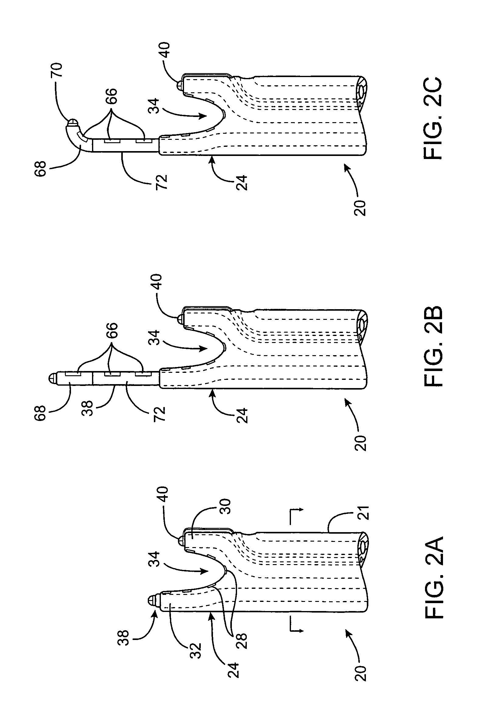
[0038]In still another aspect of the present invention, the device has a flexible tip which facilitates advancement of the device. The tip preferably extends for at least two inches and is free of any ablating elements. The tip is also preferably removable so that the tip also does not interfere with creating a closed loop.
Problems solved by technology
This location creates significant difficulties for endocardial ablation devices for several reasons.
Second, the elongated and flexible endovascular ablation devices are difficult to manipulate into the complex geometries required for forming the pulmonary venous lesions and to maintain in such positions against the wall of the beating heart.
This is very time-consuming and can result in lesions which do not completely encircle the pulmonary veins or which contain gaps and discontinuities.
Third, visualization of endocardial anatomy and endovascular devices is often inadequate and knowing the
Method used
Image
Click on the blue label to locate the original text in one second.
Reading with bidirectional positioning of images and text.
Examples
Embodiment Construction
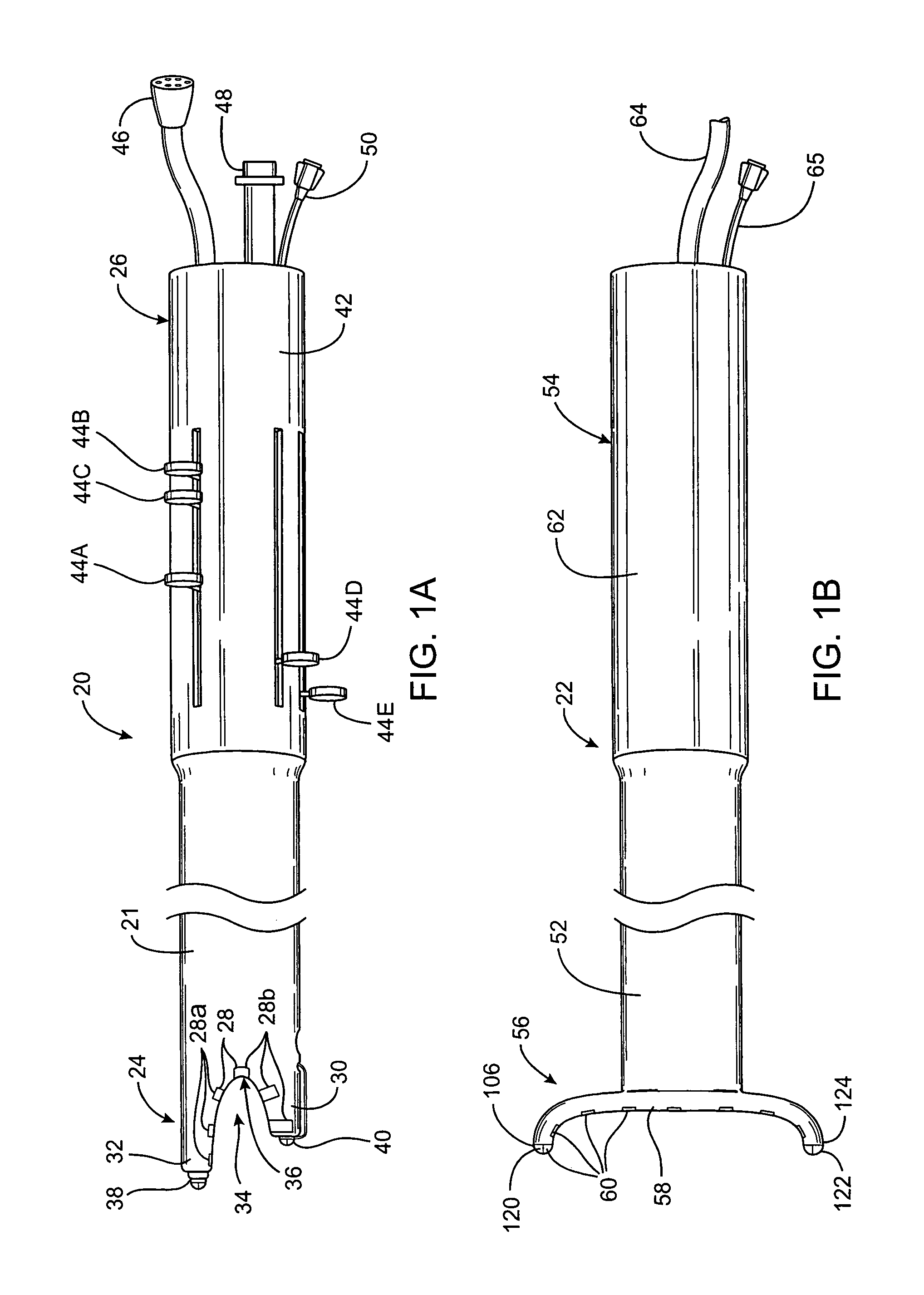
[0153]FIGS. 1A–1B illustrate a first embodiment of the apparatus of the invention. In this embodiment, the apparatus comprises a left ablation probe 20, shown in FIG. 1A, and a right ablation probe 22, shown in FIG. 1B, which work in tandem to form a transmural lesion isolating the pulmonary veins from the surrounding myocardium. Left ablation probe 20 has a flexible shaft 21 extending to a working end 24 configured for insertion into the chest cavity through a small incision, puncture or access port. Opposite working end 24, shaft 21 is attached to a control end 26 used for manipulating the working end 24 from outside the chest. Shaft 21 is dimensioned to allow introduction through a small incision in the chest, preferably in a subxiphoid location, and advanced to the pulmonary veins on the posterior side of the heart. Preferably, shaft 21 is configured to be flexible about a first transverse axis to allow anterior-posterior bending and torsional flexibility, but relatively stiff a...
PUM
Abstract
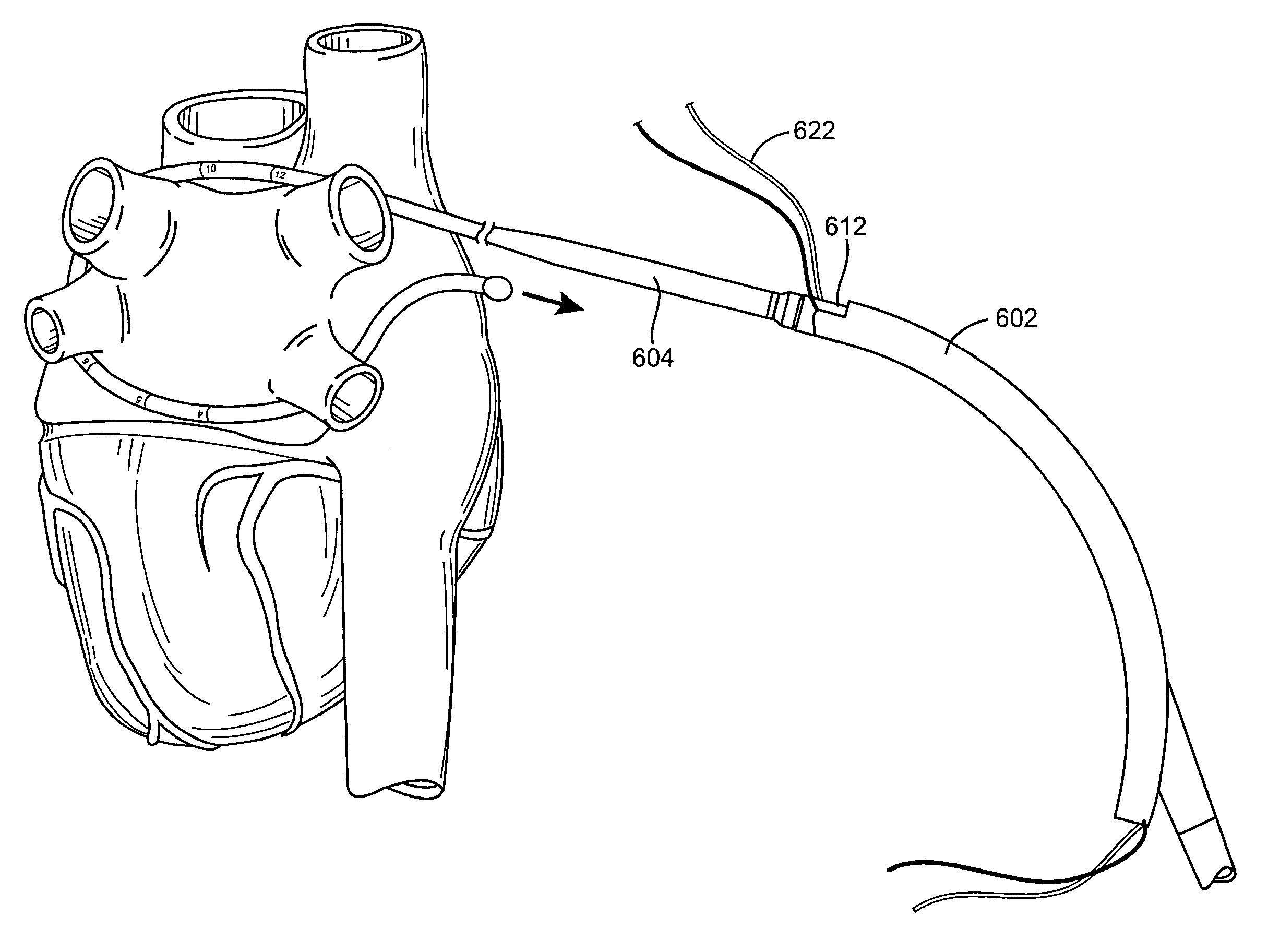
The invention is related to methods of sizing an area around the pulmonary veins along an epicardial surface. A sizing element is provided which has a plurality of indicators along its length which is used to size an area around the pulmonary veins. A sizing element is wrapped around the pulmonary veins along an epicardial location. The size of an ablating device is determined by using the indicators on the sizing element. An ablating device is then selected based on this measurement. The ablating device is then attached to the sizing element. The ablating device is then wrapped around the pulmonary veins while manipulating the sizing element.
Description
CROSS-REFERENCE TO RELATED APPLICATIONS[0001]The present application is a continuation-in-part of application Ser. No. 10 / 077,470, filed Feb. 15, 2002, now U.S. Pat. No. 6,840,936, which is a continuation-in-part of application Ser. No. 09 / 884,435, filed Jun. 19, 2001, now U.S. Pat. No. 6,719,755, which is a continuation-in-part of application Ser. No. 09 / 614,991, filed Jul. 12, 2000, now U.S. Pat. No. 6,805,128, which is a continuation-in-part of application Ser. No. 09 / 507,336 filed Feb. 18, 2000, which is a continuation-in-part of application Ser. No. 09 / 356,476, filed Jul. 19, 1999, now U.S. Pat. No. 6,311,692, which is a continuation-in-part of application Ser. No. 09 / 157,824, filed Sep. 21, 1998, now U.S. Pat. No. 6,237,605, which is a continuation-in-part of application Ser. No. 08 / 943,683, now U.S. Pat. No. 6,161,543, filed Oct. 15, 1997, which is a continuation-in-part of application Ser. No. 08 / 735,036, filed Oct. 22, 1996, now abandoned, the full disclosures of which are ...
Claims
Application Information
Patent Timeline
Application Date:The date an application was filed.
Publication Date:The date a patent or application was officially published.
First Publication Date:The earliest publication date of a patent with the same application number.
Issue Date:Publication date of the patent grant document.
PCT Entry Date:The Entry date of PCT National Phase.
Estimated Expiry Date:The statutory expiry date of a patent right according to the Patent Law, and it is the longest term of protection that the patent right can achieve without the termination of the patent right due to other reasons(Term extension factor has been taken into account ).
Invalid Date:Actual expiry date is based on effective date or publication date of legal transaction data of invalid patent.

