Control magnetic bearing device

a magnetic bearing and control technology, applied in the direction of electric controllers, automatic control, instruments, etc., can solve the problems of varying the rotational speed of the motor, failing to maintain the gas discharge performance of the pump at a constant level, and the device becomes large and more costly to manufacture, so as to reduce the size and cost

Inactive Publication Date: 2006-05-30
KOYO SEIKO CO LTD
View PDF26 Cites 44 Cited by
  • Summary
  • Abstract
  • Description
  • Claims
  • Application Information

AI Technical Summary

Benefits of technology

[0007]An object of the present invention is to solve the above problem and to provide a control magnetic bearing device wherein fluctuations in the motor current due to fluctuations in the input voltage from the power source unit can be suppressed and which is reduced in size and cost.
[0011]The main control unit controls the inverter so as not to produce variations in the motor current even if the input voltage from the power source unit fluctuates.
[0012]With the control magnetic bearing device of the invention, the inverter is controlled in accordance with the input voltage value from the power source unit, whereby variations in the motor current due to fluctuations in the input voltage value from the power source unit can be suppressed, consequently suppressing variations in the rotational speed of the motor due to fluctuations in the input voltage value. In the case where the device is incorporated, for example, into a turbo-molecular pump, the pump is capable of exhibiting constant gas discharge performance. Since the main control unit has software-programmable digital processing means for controlling the inverter, the device is serviceable for the pump merely by modifying the software only without the necessity of additionally using a constant-voltage circuit or like hardware. This renders the device reduced in size and less costly.
[0015]In this way, the motor current can be made to remain free of variations for the same command current value even if the input voltage value fluctuates.
[0018]Even if the input voltage value fluctuates, the maximum value of the motor current is made constant in this way to suppress variations in the maximum value of the motor current.

Problems solved by technology

However, the conventional magnetic bearing device has the problem that when the input voltage from the power source unit to the inverter involves fluctuations due to voltage variations of the external power source, the motor current (the current actually flowing through the electric motor) also fluctuates correspondingly, consequently varying the rotational speed of the motor and failing to maintain the gas discharge performance of the pump at a constant level.
The motor current variation can be eliminated by adding a constant-voltage circuit or like hardware to the main control unit, but the device then becomes large-sized and more costly to manufacture.

Method used


Image

  • Control magnetic bearing device
  • Control magnetic bearing device
  • Control magnetic bearing device

Examples


Embodiment Construction

[0023]The present invention as applied to a turbo-molecular pump will be described below with reference to the drawings.

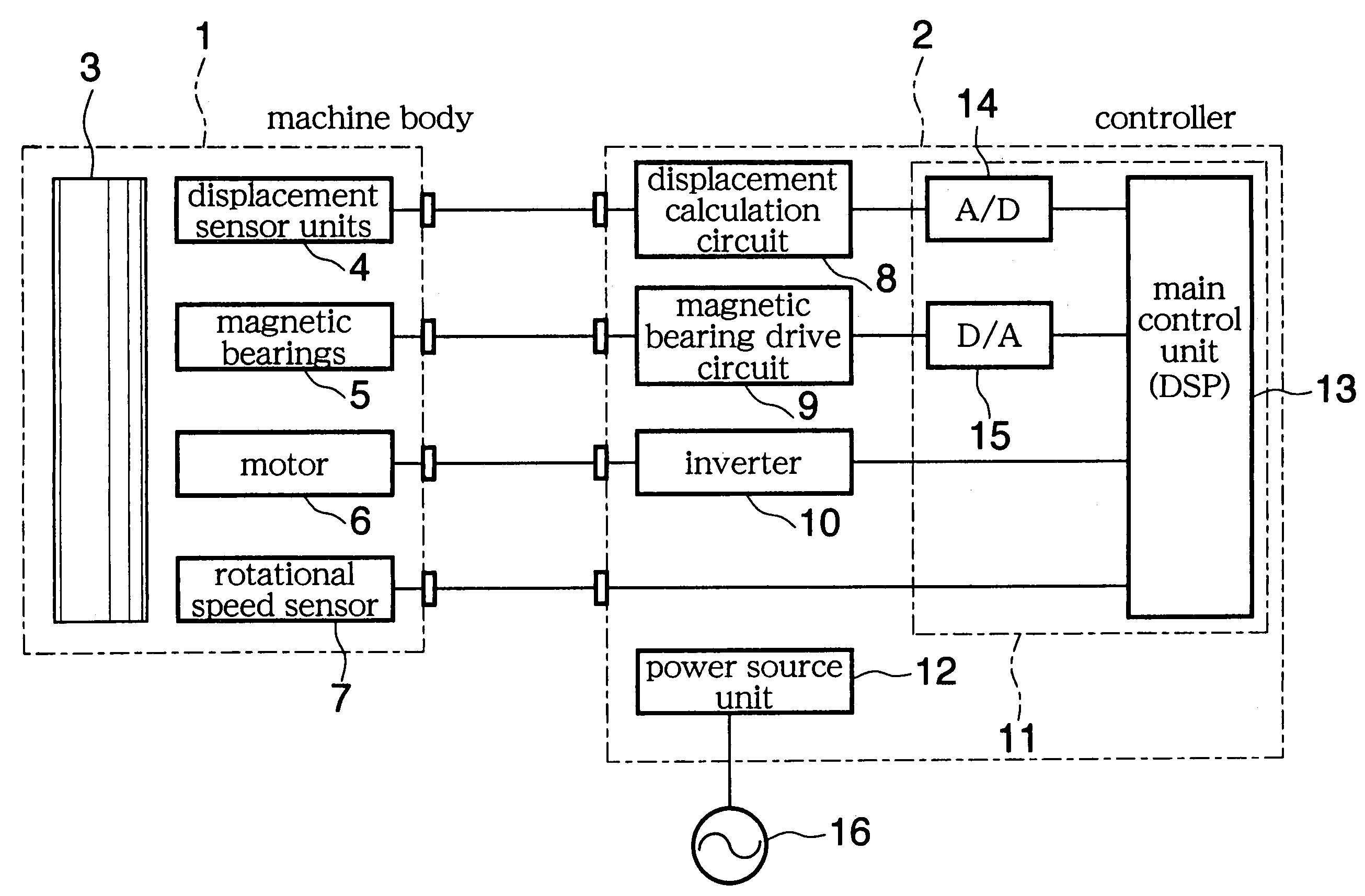
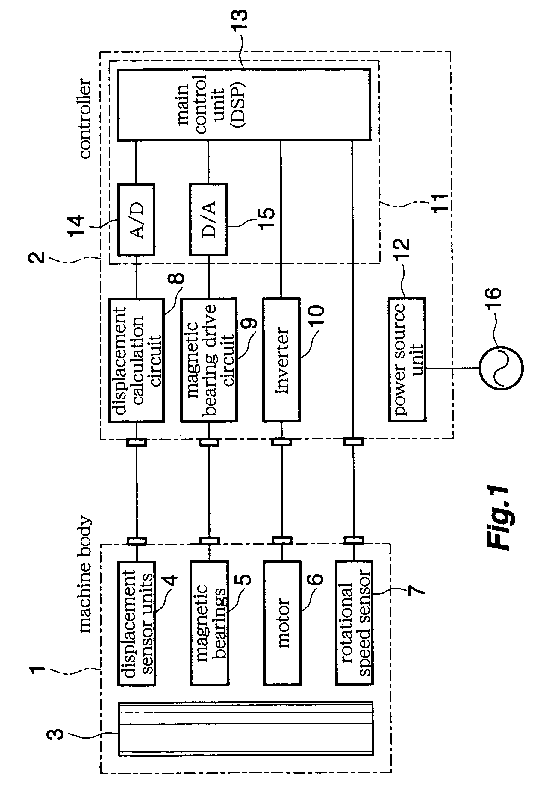
[0024]FIG. 1 schematically shows the construction of the turbo-molecular pump.

[0025]The pump comprises a machine body 1 providing a pump main body, and a controller 2 providing a pump control unit serving as control means.

[0026]The machine body 1 has a rotor (pump rotor) 3 constituting a pump, displacement sensor units 4, control magnetic bearings 5, an induction machine which is, for example, a built-in electric motor 6, and a rotational speed sensor 7 serving as a rotation speed detecting means.

[0027]The controller 2 has a displacement calculation circuit 8, magnetic bearing drive circuit 9, inverter 10, DSP board 11 and power source unit 12. The DSP board 11 has a main control unit 13, AD converter 14 and DA converter 15.

[0028]The magnetic bearings 5 include a control axial magnetic bearing disposed at one location along the axial direction of the rotor 3 for co...


PUM


Abstract

A control magnetic bearing device comprises a plurality of control magnetic bearings for contactlessly supporting a rotor, an electric motor for rotating the rotor, a magnetic bearing drive circuit for driving the magnetic bearings, an inverter for driving the electric motor, a main control circuit for controlling the magnetic bearing drive circuit and the inverter, and a power source unit connected to an external power source for supplying electric power to the magnetic bearing drive circuit, the inverter and the main control unit. The main control unit has software-programmable digital processing means for controlling the inverter in accordance with an input voltage value from the power source unit.

Description

[0001]This application is a continuation of application Ser. No. 10 / 774,424 filed on Feb. 10, 2004, now abandoned.BACKGROUND OF THE INVENTION[0002]The present invention relates to magnetic bearing devices of the control type, for example, for use in turbo-molecular pumps.[0003]Magnetic bearing devices of the type mentioned comprise a rotor contactlessly supported by a plurality of control magnetic bearings and rotatable by an electric motor to be driven by an inverter. Electric power is supplied from an external power source, i.e., a commercial AC power source (200 V), to a power source unit for supplying electric power (direct current), for example, to the inverter, a magnetic bearing drive circuit and a main control unit for controlling these components. The power source unit rectifies and smooths the alternating current from the commercial power source and supplies the resulting current to the inverter, etc.[0004]However, the conventional magnetic bearing device has the problem t...

Claims


Application Information

Patent Timeline
Patent Type & Authority Patents(United States)
IPC IPC(8): G05D23/275H02K5/24H02K7/09
CPCF16C32/0455H02K7/09F16C2380/26F16C2360/45
Inventor UEYAMA, HIROCHIKAMIYAGAWA, YASUKATA
Owner KOYO SEIKO CO LTD
Why Eureka
Try Eureka