
Encapsulation of a magnetic resonance tomography device for attenuation of low sound frequencies

a magnetic resonance tomography and low sound frequency technology, applied in the field of magnetic resonance tomography, can solve the problems of disturbing the patient, the operating personnel and other people in the vicinity of the mr device, the effect of the mr system, and the generation of extremely high air-borne noise, so as to reduce the noise transmission during the operation. , the effect of simple and economical manner

Inactive Publication Date: 2006-05-30
SIEMENS HEALTHCARE GMBH
View PDF7 Cites 22 Cited by
  • Summary
  • Abstract
  • Description
  • Claims
  • Application Information

AI Technical Summary

Benefits of technology

[0030]An object of the present invention is to reduce further the noise transmission during operation of an MRT device in the entire relevant frequency range (50–2000 Hz) in a simple and economical manner.
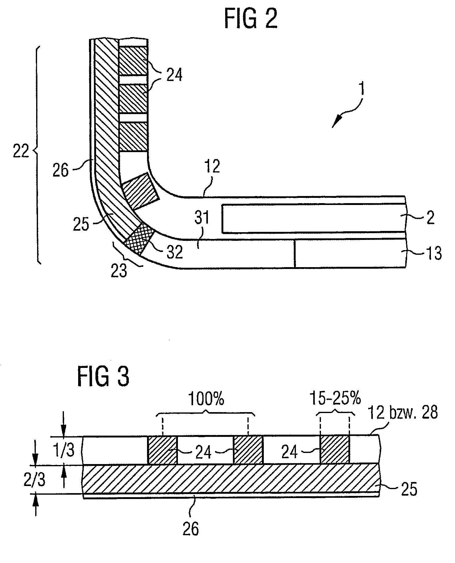
[0032]Both embodiments of the MRT device according to the invention are acoustically identical. The first embodiment of the capsule has the advantage that a partial foam layer configured as the inner layer allows tolerance compensation, as a non-solid layer can adapt more easily to unplanned deformations in the magnet shell. The cover layer advantageously has a high mass per unit area.
[0040]To reduce vibration further the outer ends of the carrier tube extension pieces are advantageously provided with reinforcing rings.

Problems solved by technology

Vibration of the different MR components has a negative effect on the MR system in many ways:1. An extremely high level of air-borne noise is generated, which is disturbing for the patient, the operating personnel and other people in the vicinity of the MR device.
2. The vibration of the gradient coil and the basic field magnet and the transmission of said vibration to the RF resonator in the inner area of the basic field magnet or the gradient coil is manifested in inadequate clinical image quality, which can even result in misdiagnosis (e.g. with functional imaging fMRI).3. If the vibration of the magnet shell—i.e. the outer tank—is transmitted via the glass fiber reinforced plastic rods to the inner tank or the superconductor itself is stimulated to vibrate, a higher level of helium evaporation takes place—as with an ultrasonic atomizer—thereby incurring higher costs.< / ul
Firstly, the large surfaces of the copper film that are conventionally inserted relatively loosely in a carrier tube with a paper lattice structure were significantly reduced by “slots”.
Secondly these films were connected rigidly and permanently to the carrier tube so that only vibration of the carrier tube could also result in vibration of the copper conductive surfaces.
Thirdly, vibration of the carrier tube was impeded by significantly increasing the mass of the carrier tube using other materials.
Despite these modifications further noise transmission still occurs from the gradient coil to the RF resonator and also to the magnet shell.

Method used


Image

  • Encapsulation of a magnetic resonance tomography device for attenuation of low sound frequencies
  • Encapsulation of a magnetic resonance tomography device for attenuation of low sound frequencies
  • Encapsulation of a magnetic resonance tomography device for attenuation of low sound frequencies

Examples


Embodiment Construction

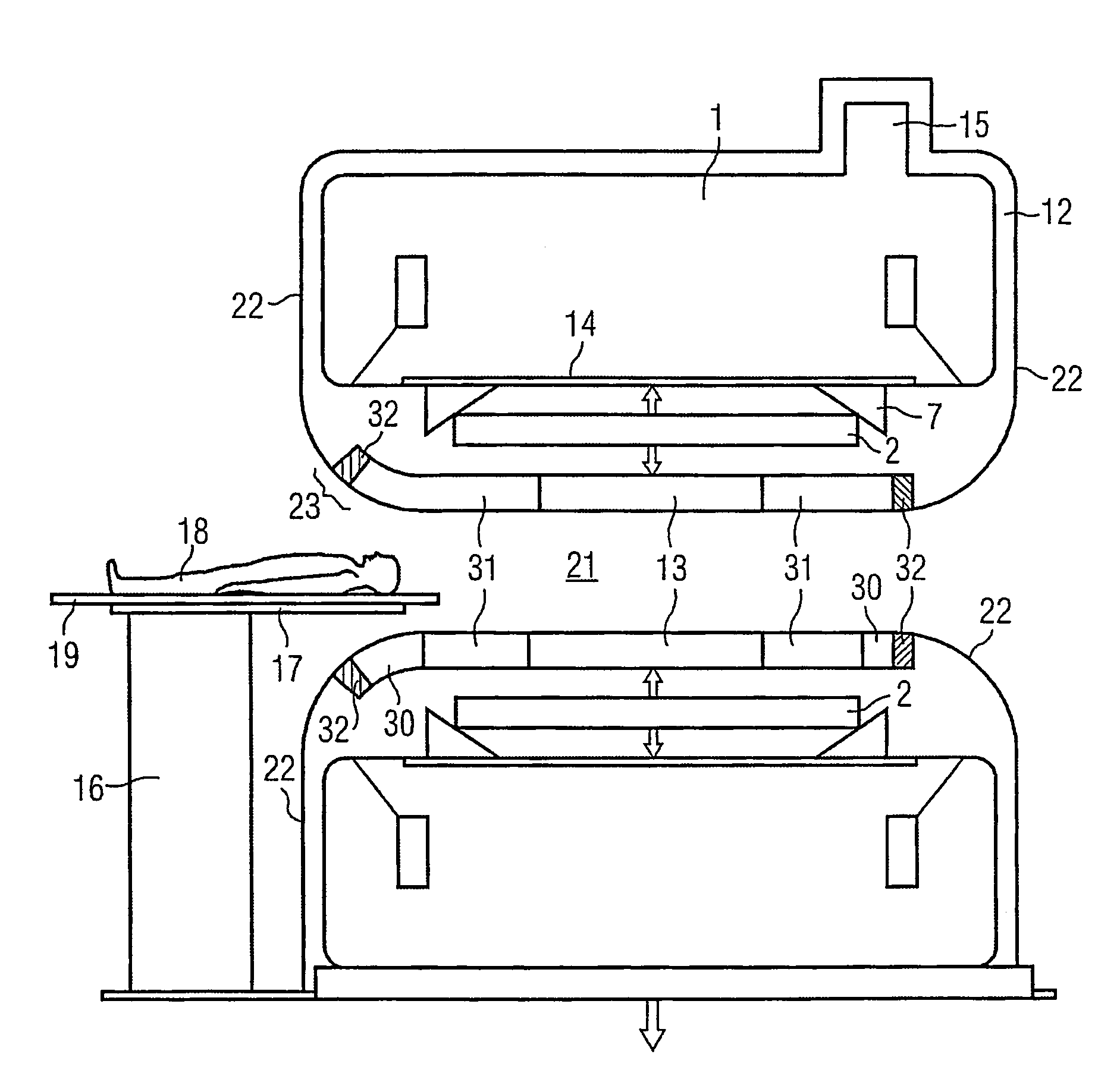
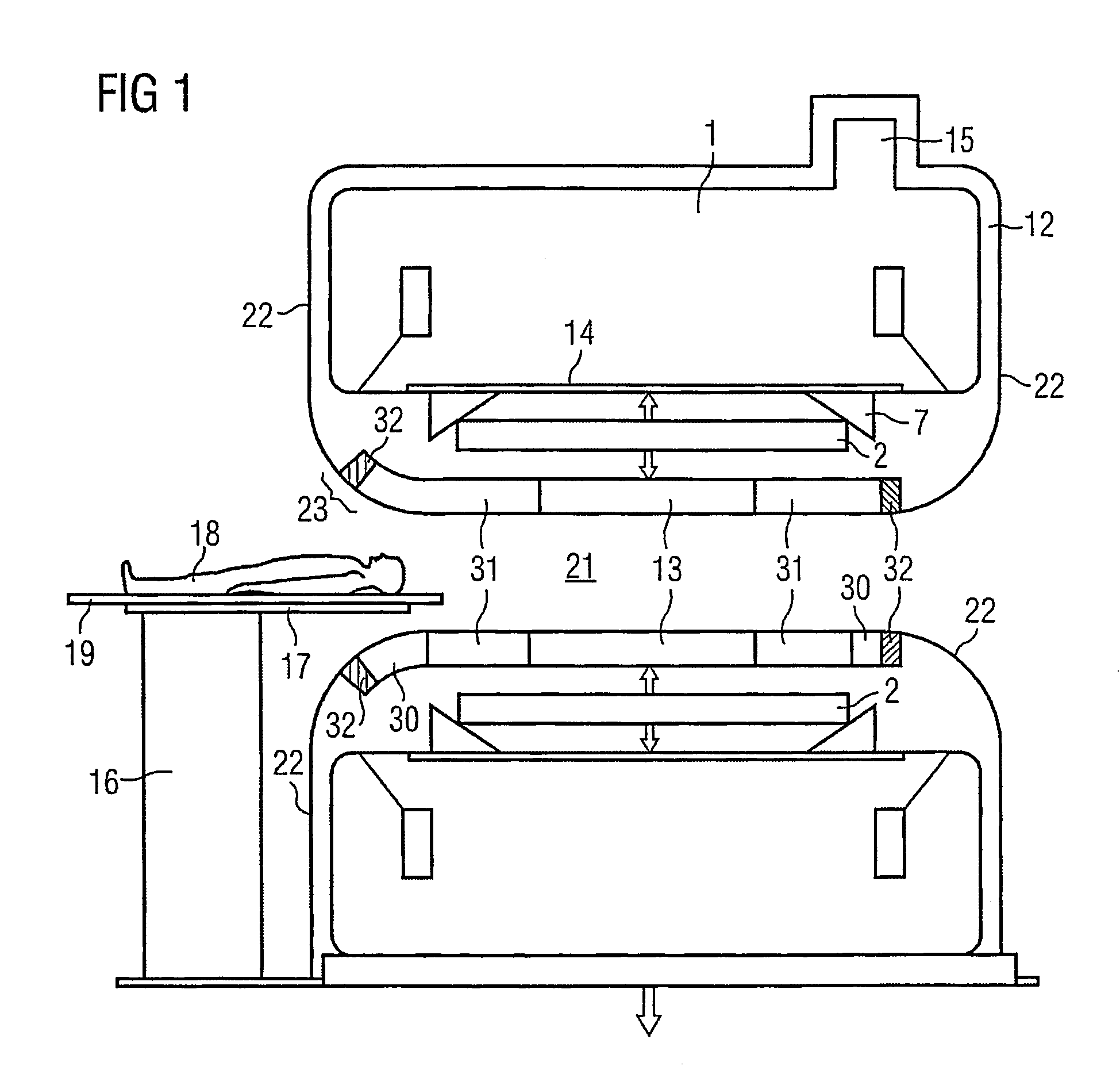
[0054]The principal vibration source or vibration center—apart from the cold head—of a conventional MRT device according to the prior art, as shown for example schematically in FIG. 8, is the gradient coil system 2. The present invention allows noise transmission and noise emission, particularly in the low frequency range (50–200 Hz) to be significantly reduced by three measures or a combination of said three measures.

[0055]The measures are:[0056]A) Encapsulation of the magnet shell and gradient coil using a cantilevered layer structure, the structural rigidity of which is less than that of the materials used,[0057]B) Modification of the RF resonator and tongues configured as a body coil (BC),[0058]C) Acoustically optimized configuration of cutouts in the inventive encapsulation.

[0059]The above inventive measures result in an inventively modified MRT device, as shown in FIG. 1. The original cladding 29 is replaced by the inventive encapsulation 22, which is connected at an acoustica...


PUM

PropertyMeasurementUnit
widthaaaaaaaaaa
current rise ratesaaaaaaaaaa
frequencyaaaaaaaaaa

Abstract

A magnetic resonance tomography device, wherein vibrations of device components, particularly in the low frequency range, are attenuated, as a magnet body surrounded by a magnet shell, which surrounds and defines an inner area. A gradient coil system is disposed in the inner area and an inner encapsulation cylinder also is disposed therein. The magnetic shell and the gradient coil system are externally and acoustically sealed from the inner encapsulation cylinder, and from a capsule. The capsule is formed as a three-layer system, including a cover layer, a full foam layer and a partial foam layer.

Description

BACKGROUND OF THE INVENTION[0001]1. Field of the Invention[0002]The present invention relates generally to magnetic resonance tomography (MRT) used in medicine to examine patients. The present invention relates especially to a magnetic resonance tomography device, wherein vibrations of device components especially in the low frequency range are attenuated by encapsulation of the MRT device.[0003]2. Description of the Prior Art[0004]MRT is based on the physical phenomenon of nuclear magnetic resonance and has been used successfully as an imaging method in medicine and biophysics for more than 15 years. With this examination method the subject is exposed to a powerful and constant magnetic field. As a result, the previously random nuclear spins of the atoms in the subject are aligned. Radio frequency energy can now stimulate these “ordered” nuclear spins to a specific vibration. This oscillation generates the actual measurement signal in MRT and this is detected by suitable receiver c...

Claims


Application Information

Patent Timeline
Patent Type & Authority Patents(United States)
IPC IPC(8): H01F5/00G01R33/385
CPCG01R33/3854
Inventor ARZ, WINFRIEDDIETZ, PETERDISTLER, PETERFRANZKE, UDOWEBER, MATTHIAS
Owner SIEMENS HEALTHCARE GMBH
Learn More