System for high density linear serpentine data recording

a data recording and high density technology, applied in the field of linear recording, can solve the problems of inability to manufacture a head with several hundred read and write elements, inability to support the high track density of newer tape drives, and inability to achieve the effect of reducing tape and head wear

Inactive Publication Date: 2006-05-30
MOUNTAIN ENG II
View PDF5 Cites 39 Cited by
  • Summary
  • Abstract
  • Description
  • Claims
  • Application Information

AI Technical Summary

Benefits of technology

[0025]It is another object of the invention to reduce the tape and the head wear.

Problems solved by technology

Recording errors can be caused by media defects, contamination of the media, contamination of the head elements, and by other reasons.
The example shown in FIG. 2 does not support the high track density of newer tape drives.
It is not practical to manufacture a head with several hundred of read and write elements.
The large size of the head is disadvantageous for several reasons.
First, the overall size of newer tape drives is getting smaller.
A large head poses an obstacle to the miniaturization effort.
Second, the large mass of the head limits the operation of a actuator.
Third, the large number of passes of the head over the tape increases tape wear and head wear.
Manufacturing tolerances of the head, combined with inaccuracies of the tape and fluctuations of the tape movement across the head, make this precision difficult to achieve.
However, the mass of the head limits the frequency response of the system.
This limitation is undesirable since further decreases in the track width cannot be achieved without a fast track-following system.
The current method where tape flies over the head also poses a formidable obstacle when attempting to increase the linear density of tape.
When the tape moves over the recording surface of the head air gets trapped between the head surface and the tape.
An additional problem with the current method is increased tape wear and contamination of the head as a result of the tape wear.
However when tape movement is stopped, the air film dissipates and the still-moving tape contacts the head.
The friction between the tape and the head causes wear of the tape and the head.
This wear limits the lifetime of both the tape and the head.
In addition, loose particles of debris collect on the head and on the tape, resulting in read and write errors.
Referring now again to FIG. 4, we can see that current methods are causing excessive tape wear.
However, the previously recorded data cannot be verified again when the tape moves over the head to record track group 50.
This leads to an increase in the number of times the tape passes over the read-write head before the entire tape is recorded.
The high number of passes, combined with the lack of verification, poses a serious risk to the reliability of the data.

Method used


Image

  • System for high density linear serpentine data recording
  • System for high density linear serpentine data recording
  • System for high density linear serpentine data recording

Examples


Embodiment Construction

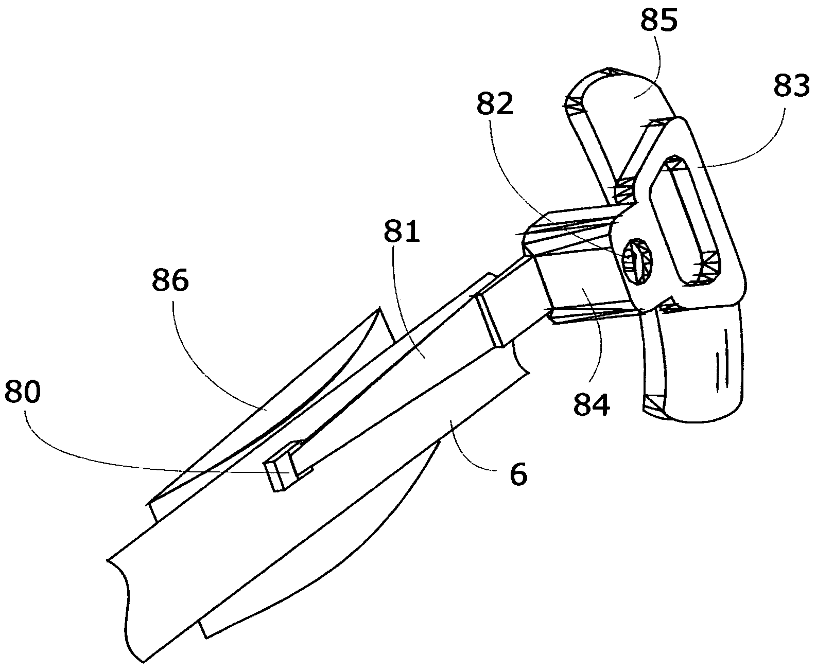
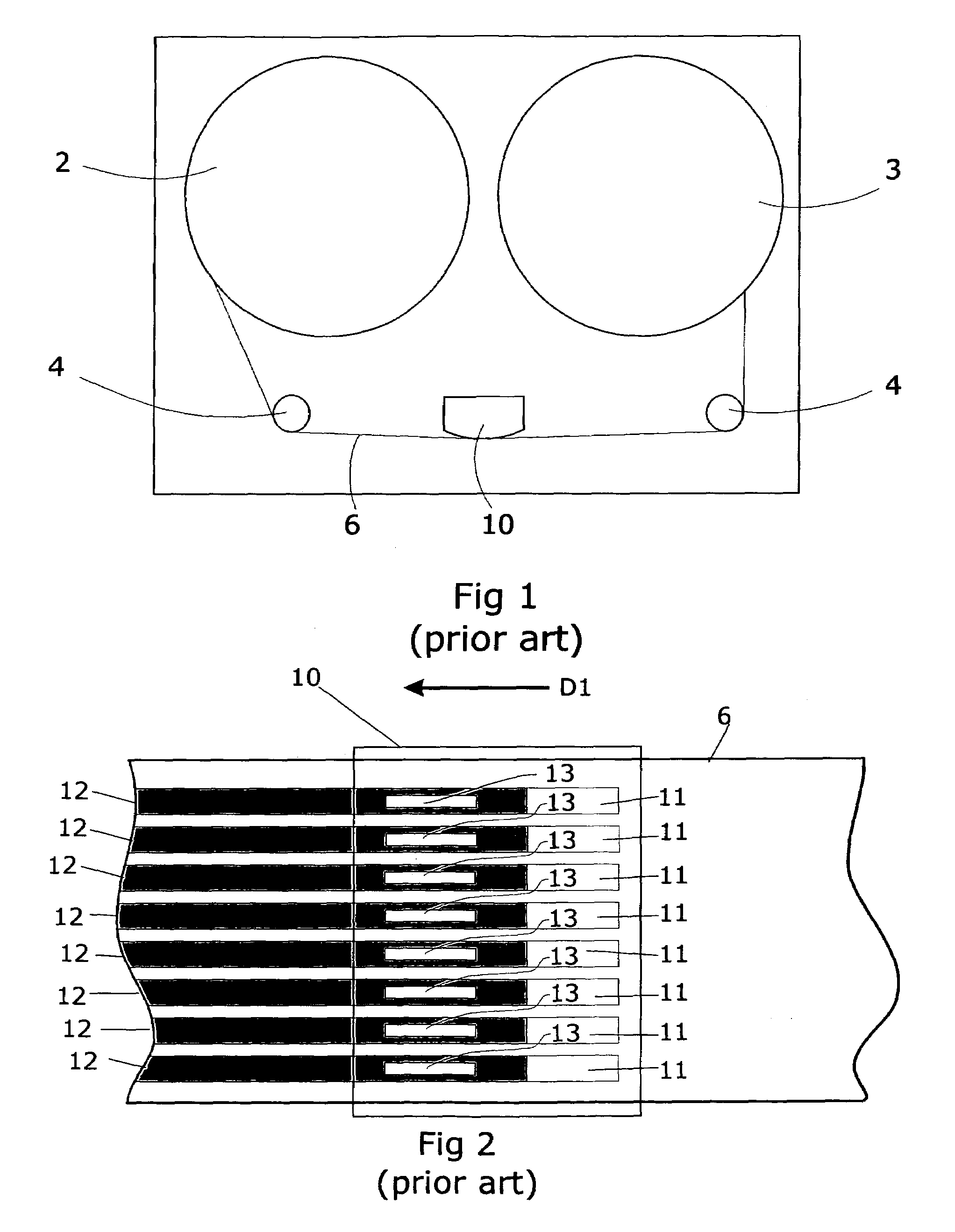
[0052]FIG. 6 shows an exemplary tape drive with the inventive head assembly 70. A take-up reel 3, two tape guides 4, and a tape cartridge 5 with an enclosed supply reel (not shown) are mounted on a base 1. The tape (not shown) is wound from the supply reel in cartridge 5 over two tape guides 4 to the take-up reel 3 past the read-write head assembly 70. The head assembly 70 is shown in greater detail in FIG. 7a.

[0053]A base 71 contains an actuator that is capable of moving the read-write head in the directions of arrow A. Actuators of many different designs are known. Voice coil driven actuators are used in high performance tape drives because of their ability to move the head at a high speed and with a fast acceleration. They can be designed to move the head over the required length so that the head elements can access all recorded areas of the tape. Actuators using piezo elements are also very fast but have a limited operating range. Actuators using motor driven lead screws are ab...


PUM

PropertyMeasurementUnit
recording areaaaaaaaaaaa
areaaaaaaaaaaa
magneticaaaaaaaaaa

Abstract

A recording system comprises a read-write head with a length that is substantially smaller than the width of the tape, the small mass of the head allows high frequency track following. The head contacts only that area of the tape currently being accessed, significantly reducing the tape and the head wear. The head flies over the tape with the flying height tightly controlled even at high tape speed and low tape tension. Several methods to stabilize the tape in the recording area are disclosed. The stabilizer can be a second recording head allowing dual sided recording. A first implementation uses a linear actuator and a second implementation uses a rotary actuator. A mechanism moves the head from the path of a threading mechanism.

Description

BACKGROUND OF INVENTION[0001]Several methods to record data on magnetic tape are known. Among those are helical scan, arcuate scan, and linear recording. The present invention relates to linear recording.[0002]A typical tape drive for linear recording is shown in FIG. 1. It comprises of a supply reel 2 and a take up reel 3. One or both reels may be enclosed in a cartridge. The tape 6 is moved under the control of a servo system (not shown) between the supply reel and the take up reel past a read-write head 10. A plurality of bearings 4 may be used to guide the tape.[0003]Linear recording devices write the data in individual data tracks parallel to the edge of the recording media. FIG. 2 depicts a typical configuration. Recording media 6 is moved in direction of arrow D1 across the surface of a read / write head 10. The head contains several write elements 11, each of which writes one data track 12 on magnetic tape 6. The head also contains a number of read elements 13. Typically, ther...

Claims


Application Information

Patent Timeline
Patent Type & Authority Patents(United States)
IPC IPC(8): G11B5/008G11B21/08G11B5/55
CPCG11B5/584G11B5/00821
Inventor MARION, JACK LGROEL, PETER L
Owner MOUNTAIN ENG II
Why Eureka
Try Eureka