Holder used in the microphone unit

a microphone and holder technology, applied in the direction of piezoelectric/electrostrictive transducers, mouthpiece/microphone attachments, microphone structural associations, etc., can solve the problems of difficult to ensure a sufficient gap between the two terminals, difficult to ensure steady electric connection between the terminals and electrically conductive patterns of the external board respectively, and low efficiency in mounting the microphone. , the amount of use of electrically conductive rubber is more expensive than the amount of electrically insul

Inactive Publication Date: 2006-05-30
STAR MICRONICS
View PDF7 Cites 14 Cited by
  • Summary
  • Abstract
  • Description
  • Claims
  • Application Information

AI Technical Summary

Benefits of technology

[0021]When the form in which the first electrically conductive portion is brought into contact with the casing from the lower side is adopted, the amount of use of electrically conductive rubber more expensive than electrically insulating rubber can be reduced. When the form in which the first electrically conductive portion is brought into contact with the casing from the outer circumferential side is

Problems solved by technology

It is however difficult to ensure a sufficient gap between the two terminals if the outer diameter of the microphone becomes smaller than a certain value.
This causes a problem that steady electric connection of the terminals

Method used


Image

  • Holder used in the microphone unit
  • Holder used in the microphone unit
  • Holder used in the microphone unit

Examples


Embodiment Construction

[0029]The present invention will be described below in detail with reference to the accompanying drawings.

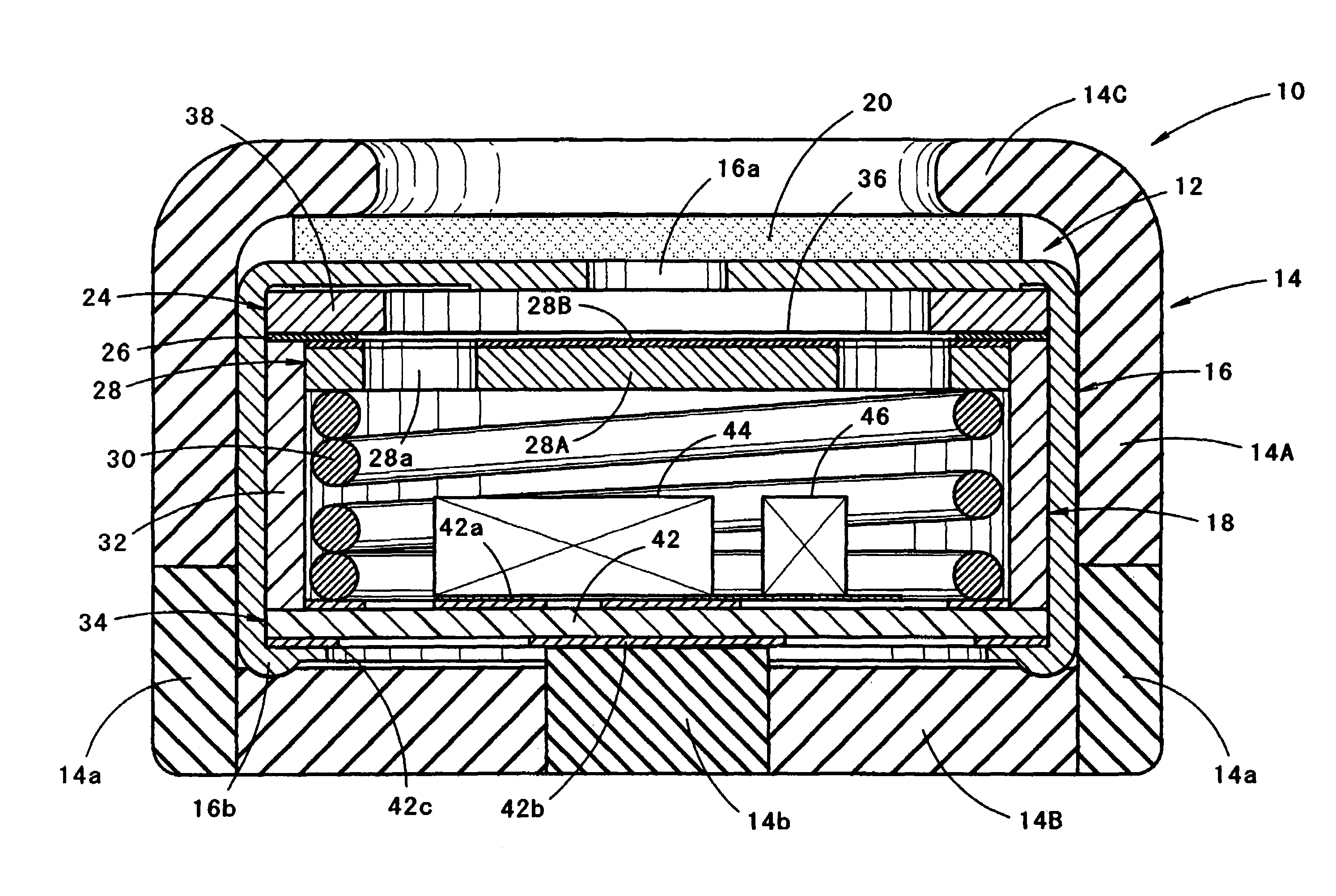
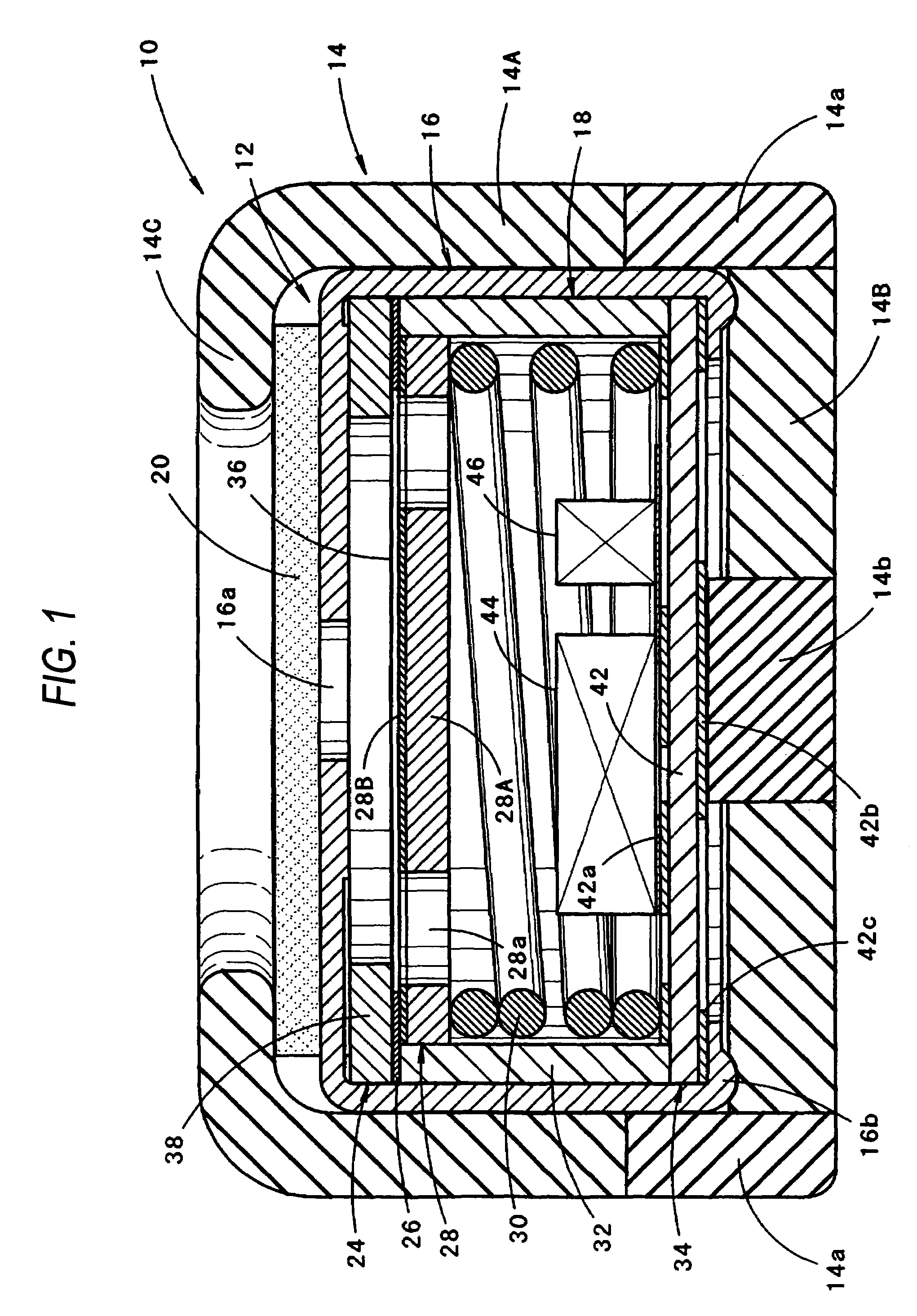
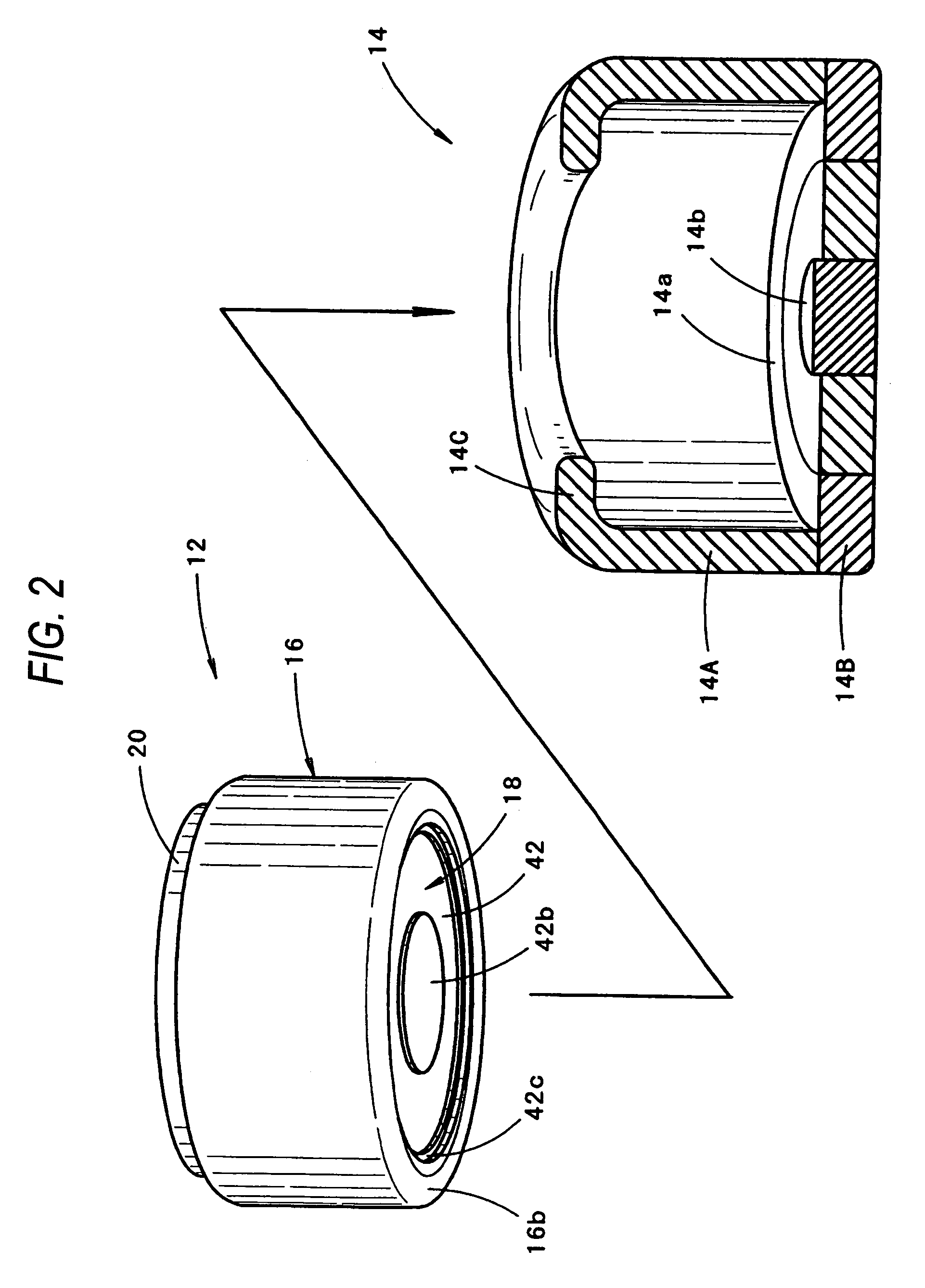
[0030]FIG. 1 is a side sectional view of a microphone unit according to an embodiment of the invention in the case where the microphone unit is disposed so as to face upward. FIG. 2 is an exploded perspective view of the microphone unit.

[0031]As shown in FIGS. 1 and 2, the microphone unit 10 according to this embodiment includes a microphone 12 having an outer circumferential surface substantially cylinder-shaped, and a rubber holder 14 for holding the microphone 12 so as to cover the microphone 12 substantially cylindrically.

[0032]The configuration of the microphone 12 will be described first.

[0033]The microphone 12 is an ultra small electret condenser microphone which includes a substantially cylindrical casing 16, a microphone body 18 stored in the casing 16, and a disk-shaped acoustic filter 20 made of non-woven fabric or the like and attached to an upper surface of the casi...


PUM


Abstract

In a microphone having a microphone body stored in a substantially cylindrical metal casing, the casing per se is formed as a ground terminal while a plus terminal is disposed in the center of a lower end surface of the microphone body. A holder is formed to have a bottom wall portion extending from a lower end portion of the holder to a lower end surface of the microphone. An outer circumferential edge portion and a center portion of the bottom wall portion are made of electrically conductive rubber so as to serve as first and second electrically conductive portions electrically connected to the two terminals respectively. Sufficient contact areas of the two electrically conductive portions with electrically conductive patterns of an external board is obtained while a sufficient gap is ensured between the two electrically conductive portions.

Description

BACKGROUND OF THE INVENTION[0001]1. Field of the Invention[0002]The present invention relates to a microphone unit having a microphone held in a rubber holder, and to the holder used in the microphone unit.[0003]2. Description of the Related Art[0004]Japanese Patent No. 3,244,448 discloses a small-size microphone mounted in a cellular phone. The microphone has an outer circumferential surface substantially cylinder-shaped, and a lower end surface on which a ground terminal and a plus terminal are disposed. The ground and plus terminals are provided so as to be electrically connected to electrically conductive patterns on a board (hereinafter referred to as “external board”) in the cellular phone.[0005]The microphone is mounted on the external board while the microphone is held in a rubber holder so as to be substantially cylindrically covered with the rubber holder for the purpose of prevention of sound leakage, positioning, etc.[0006]Reduction in microphone size has advanced in rec...

Claims


Application Information

Patent Timeline
IPC IPC(8): H04R25/00H04R1/02H04R1/04H04R1/06H04R1/08
CPCH04R1/06H04R1/083H04R2499/11
Inventor ITO, MOTOAKITSUKIJI, YOSHIAKI
Owner STAR MICRONICS
Why Eureka
Try Eureka