
Apparatus and method for responding to a interruption of a packet flow to a high level data link controller in a signal processing system

a signal processing system and packet flow technology, applied in the field of data processing systems, can solve the problems of inefficient use of semiconductor materials and components in each subsystem

Inactive Publication Date: 2006-05-30
TEXAS INSTR INC
View PDF12 Cites 14 Cited by
  • Summary
  • Abstract
  • Description
  • Claims
  • Application Information

AI Technical Summary

Benefits of technology

The present invention provides a data processing subsystem with multiple digital signal processor subsystems, a shared memory subsystem, and a global direct memory access subsystem on a chip. The global direct memory access unit includes a peripheral direct memory access unit and a high level data link controller. The high level data link controller includes a FIFO memory that receives signal groups from a plurality of storage units in the peripheral direct memory access unit. The high level data link controller reads signal groups from a location in the FIFO memory unit and transmits the signal groups as part of a packet. When an interruption in the flow of signal groups from the peripheral direct memory access unit to the FIFO memory unit results in a void in the packet, then an ABORT signal is provided to the digital signal processing component issuing the aborted packet. In addition, a message is sent to the address to which the packet is being sent indicated the previous (incomplete) packet should be disregarded. The technical effect of the present invention is to provide a more efficient and effective data processing system with improved signal processing capabilities.

Problems solved by technology

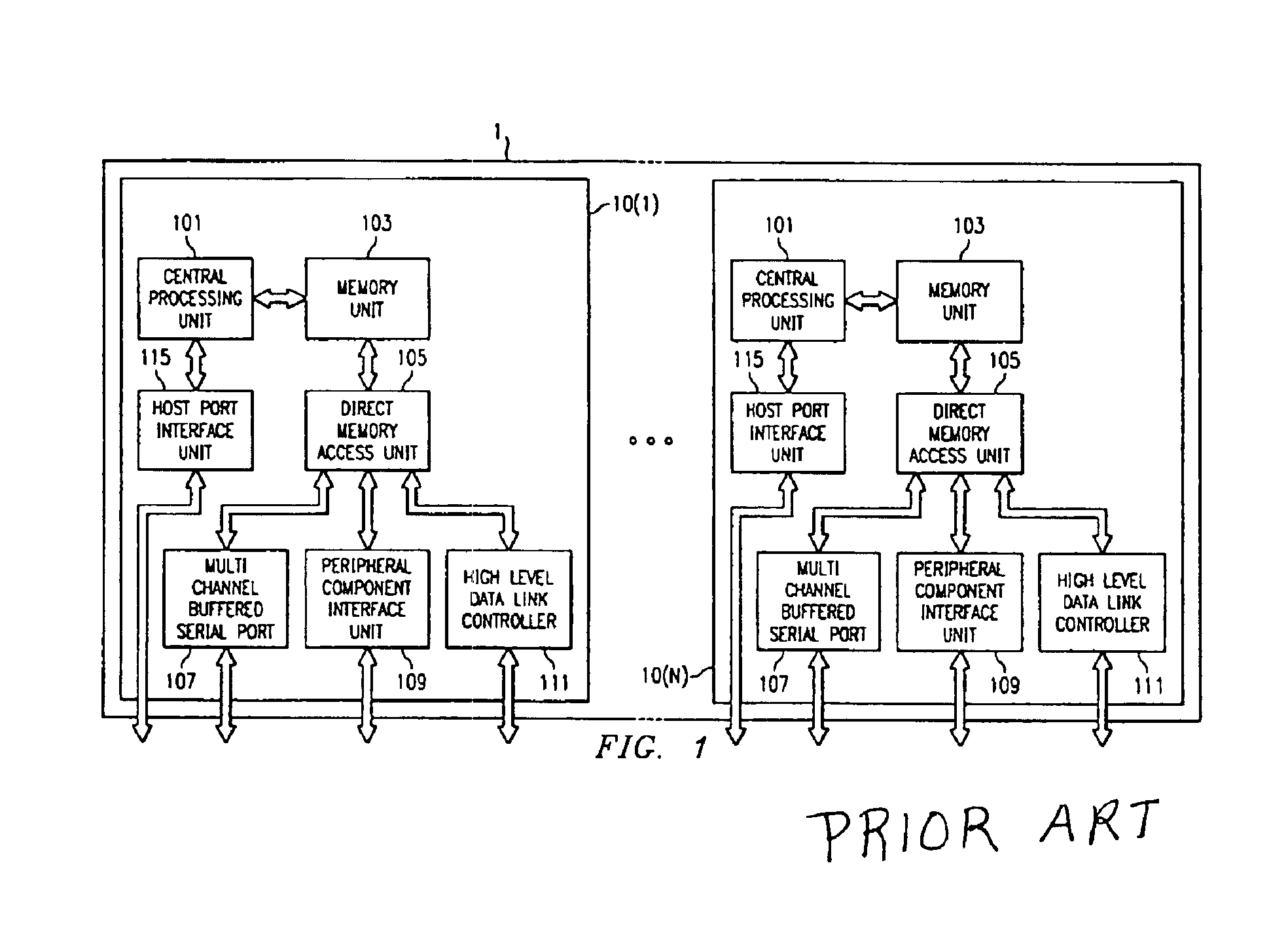
However, the result of provision of a complete set of interface units with each subsystem is an inefficient use of the semiconductor material and components.

Method used


Image

  • Apparatus and method for responding to a interruption of a packet flow to a high level data link controller in a signal processing system
  • Apparatus and method for responding to a interruption of a packet flow to a high level data link controller in a signal processing system
  • Apparatus and method for responding to a interruption of a packet flow to a high level data link controller in a signal processing system

Examples


Embodiment Construction

[0015]1. Detailed Description of the Figures

[0016]FIG. 1 has been described with respect to the related art.

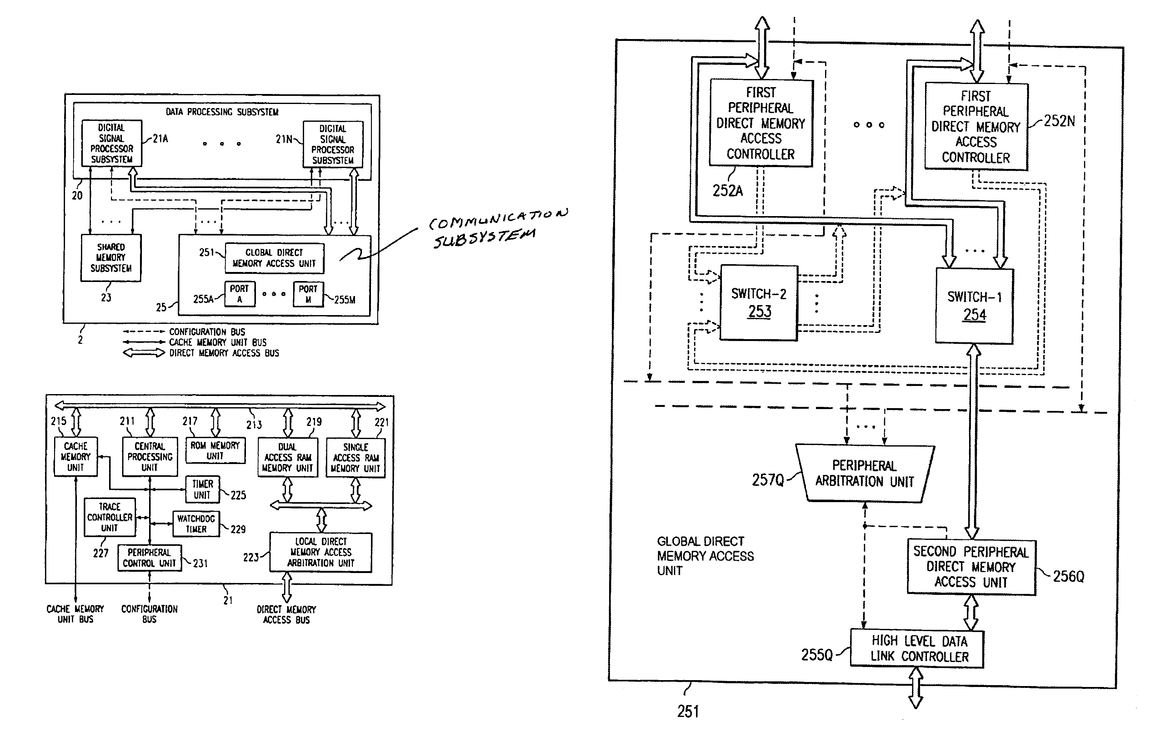
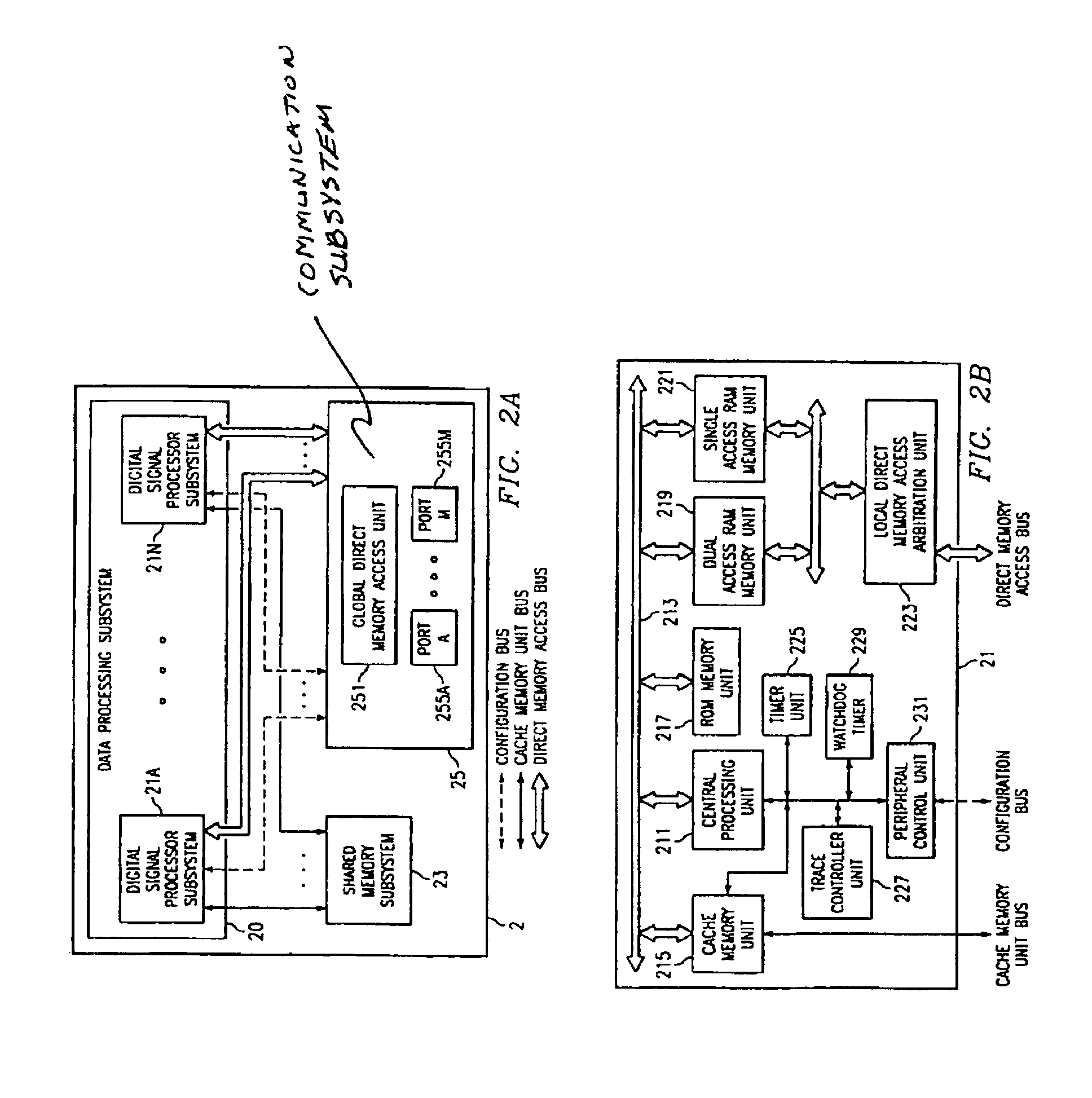
[0017]Referring to FIG. 2A, a block diagram illustrating the subsystems of a data processing system 2 capable of advantageously using the present invention is shown. The data processing system 2 includes a data processing subsystem 20, a shared memory subsystem 23 and a communication subsystem 25. The data processing subsystem 20 includes a plurality of digital signal processing subsystems 21A through 21N. The communication subsystem includes a global direct memory access unit 251 and a plurality of signal exchange ports 25A through 25M. Each digital signal processor subsystem 21A through 21N is coupled to the shared memory subsystem 24 by a cache memory unit bus represented by a solid line. Each digital signal processor subsystem 21A through 21N is coupled to the communication subsystem 25 by a configuration bus represented by a dotted line and each digital signal processor s...


PUM


Abstract

In a data processing system including a plurality of digital signal processor subsystems, selected peripheral components are shared by the digital signal processor subsystems. In particular, the high level data link controller is shared by the subsystems. Using a first interrupt signal after each transfer of signal groups from the peripheral direct memory access unit, the data can be efficiently transferred from a channel memory of the peripheral direct memory access unit to the high level data link controller. A second interrupt from the high level data link controller when a last word of a packet is transferred thereto causes a new channel memory to be accessed. An abort signal is generated when a signal group for a packet being processed by the high level data link controller is not available in a timely manner.

Description

RELATED APPLICATIONS[0001]U.S. patent application Ser. No. 10 / 001,152, entitled APPARATUS AND METHOD FOR DISTRIBUTION OF SIGNALS FROM A HIGH LEVEL DATA LINK CONTROLLER TO MULTIPLE DIGITAL SIGNAL PROCESSOR CORES, invented by Patrick J. Smith, Jay B. Reimer, Raxnesh A. Iyer, and Henry D. Nguyen, filed on even date herewith and assigned to the assignee of the present Application and U.S. patent application Ser. No. 10 / 000,990, entitled APPARATUS AND METHOD FOR CONTROLLING BLOCK SIGNAL FLOW IN A MULTI DIGITAL SIGNAL PROCESSOR CONFIGURATION FROM A SHARED PERIPHERALDIRECT MEMORY CONTROLLER TO HIGH LEVEL DATA LINK CONTROLLER, invented by Patrick J. Smith, Jay B. Reimer, Raznesh A. Iyer and Henry D. Nguyen, filed on even date herewith and assigned to the assignee of the present Application are related Applications.BACKGROUND OF THE INVENTION[0002]1. Field of the Invention[0003]This invention relates generally to data processing systems and, more particularly, to data processing systems havi...

Claims


Application Information

Patent Timeline
Patent Type & Authority Patents(United States)
IPC IPC(8): G06F13/28G06F13/38
CPCG06F13/387
Inventor IYER, RAMESH A.NGUYEN, HENRY D.SMITH, PATRICK J.REIMER, JAY B.
Owner TEXAS INSTR INC
Learn More