Trace control block implementation and method

a control block and control block technology, applied in the field of program counters and data tracing, can solve the problems of longer development time, increased workload, and significant cost of developing and debugging new software products

Inactive Publication Date: 2006-05-30
ARM FINANCE OVERSEAS LTD
View PDF86 Cites 123 Cited by
  • Summary
  • Abstract
  • Description
  • Claims
  • Application Information

AI Technical Summary

Problems solved by technology

This task represents an ever-increasing burden due to the growth in software complexity and the increase in processor clock speeds.
In general, the cost of developing and debugging new software products can be a significant factor in pr

Method used


Image

  • Trace control block implementation and method
  • Trace control block implementation and method
  • Trace control block implementation and method

Examples


Embodiment Construction

[0025]An embodiment of the invention is discussed in detail below. While specific implementations are discussed, it should be understood that this is done for illustration purposes only. A person skilled in the relevant art will recognize that other components and configurations may be used without departing from the spirit and scope of the invention.

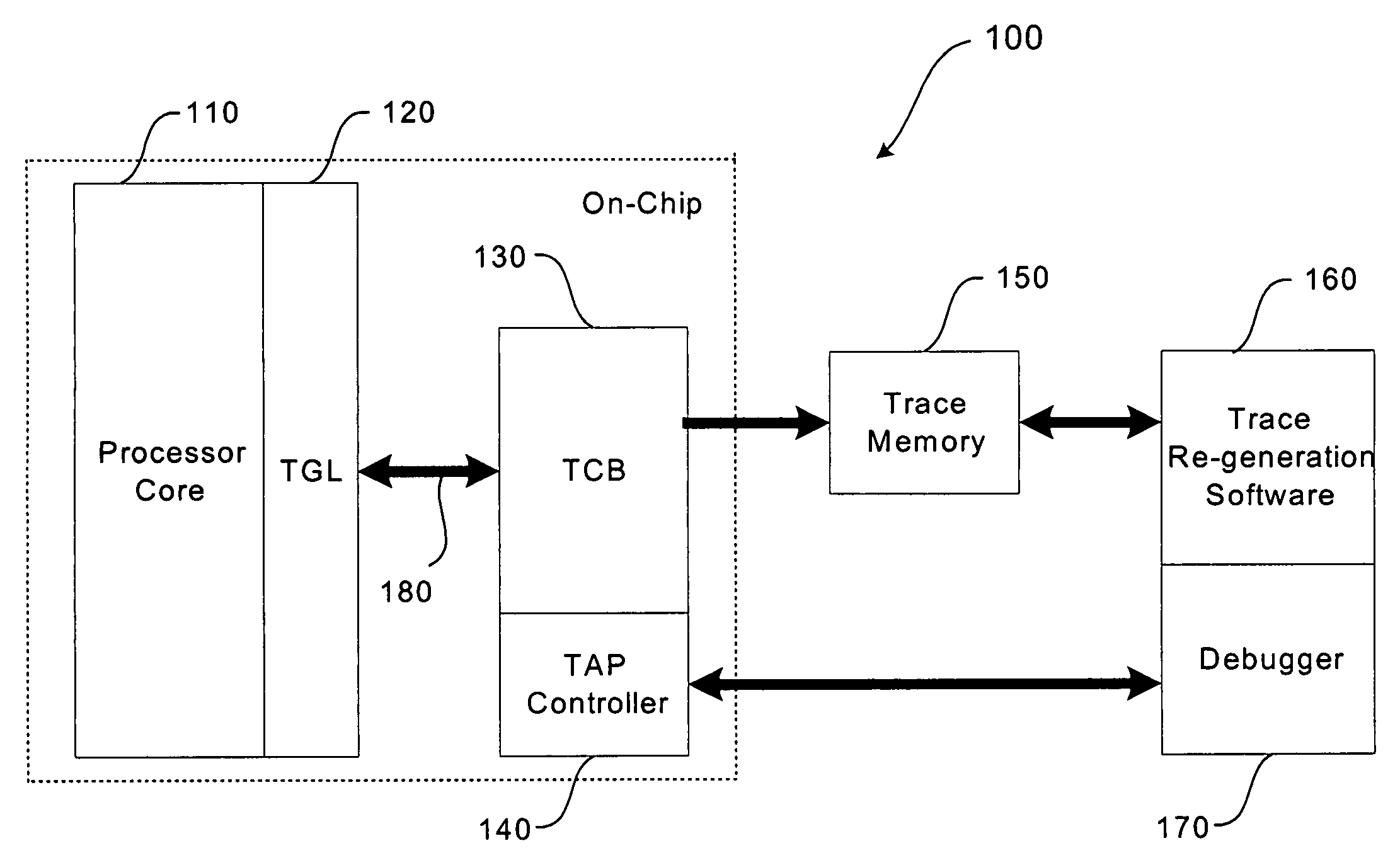
[0026]The provision of increased control and flexibility in the tracing process enables hardware, software, and computer engineers to effectively debug the operation of a computer system. These debugging efforts are enhanced when increased visibility is provided into the hardware and software state of the processor core. This is particularly true when dealing with embedded processors where specialized on-chip circuitry is often combined with the processor core. Support for these debug efforts is provided by an embodiment of a tracing system described below with reference to FIG. 1.

[0027]In the illustrated embodiment, tracing system 100 ...


PUM


Abstract

A system and method for program counter and data tracing is disclosed. A trace interface is provided for communication of trace information between a processor core and a trace control block. The trace interface enables various combinations of processor cores and trace control blocks to be implemented.

Description

[0001]The present application is a continuation-in-part application of Non-Provisional application Ser. No. 09 / 844,669, entitled “Trace Control From Hardware and Software,” filed Apr. 30, 2001, which is incorporated herein by reference in its entirety.BACKGROUND[0002]1. Field of the Invention[0003]The present invention relates generally to program counter (PC) and data tracing, and more specifically to the compressed storage of PC and data tracing information.[0004]2. Discussion of the Related Art[0005]Computer systems process information according to a program that includes a sequence of instructions defined by an application program or an operating system. Typically, a program counter provides a series of memory addresses that are used by the processor for fetching instructions stored in the associated memory. In this process, the processor conveys the memory address to the memory over an address bus, and the memory responds over an instruction / data bus with the instruction stored...

Claims


Application Information

Patent Timeline
IPC IPC(8): G06F11/00
CPCG06F11/3636
Inventor UHLER, GEORGE MICHAELTHEKKATH, RADHIKA
Owner ARM FINANCE OVERSEAS LTD
Why Eureka
Try Eureka