
Trim and glass run attachment structure in vehicle door

a technology for attaching structures and trims, which is applied in the directions of windows, transportation and packaging, wing accessories, etc., can solve the problems of difficult molding methods, difficult to set the curvature radius of the corner portion at the door opening edge of the vehicle body frame to be small, and difficult to form by molding methods. , to achieve the effect of easy movement up and down and easy formation

Inactive Publication Date: 2006-06-06
TOYODA GOSEI CO LTD
View PDF13 Cites 24 Cited by
  • Summary
  • Abstract
  • Description
  • Claims
  • Application Information

AI Technical Summary

Benefits of technology

Enables easy formation and proper positioning of the glass run, ensuring smooth operation of door glasses and enhancing the exterior appearance by stabilizing the attachment and reducing manufacturing errors.

Problems solved by technology

However, the glass run 31′ increases in size as a whole so that there is a problem in the working of attachment to the window frame 13′.
From the point of view of realization in sheet metal working, however, it is difficult to set the curvature radius of the corner portion at the door opening edge of the vehicle body frame to be small in accordance with the curvature radius of the corner portion of the door sash 17′.
Thus, there is a problem that it is difficult to form them by a molding method.
Further, there is also a problem that the attachment of the glass run 31′ to the window frame 13′ is difficult in a corner portion so that it is difficult to set the glass run 31′ in a proper position.
Then, a shortage of the pressing force causes a failure in sealing, and a gap is formed so that the exterior appearance deteriorates.
Thus, there is a problem that the door glass 14″ cannot be moved up and down smoothly.

Method used


Image

  • Trim and glass run attachment structure in vehicle door
  • Trim and glass run attachment structure in vehicle door
  • Trim and glass run attachment structure in vehicle door

Examples


Embodiment Construction

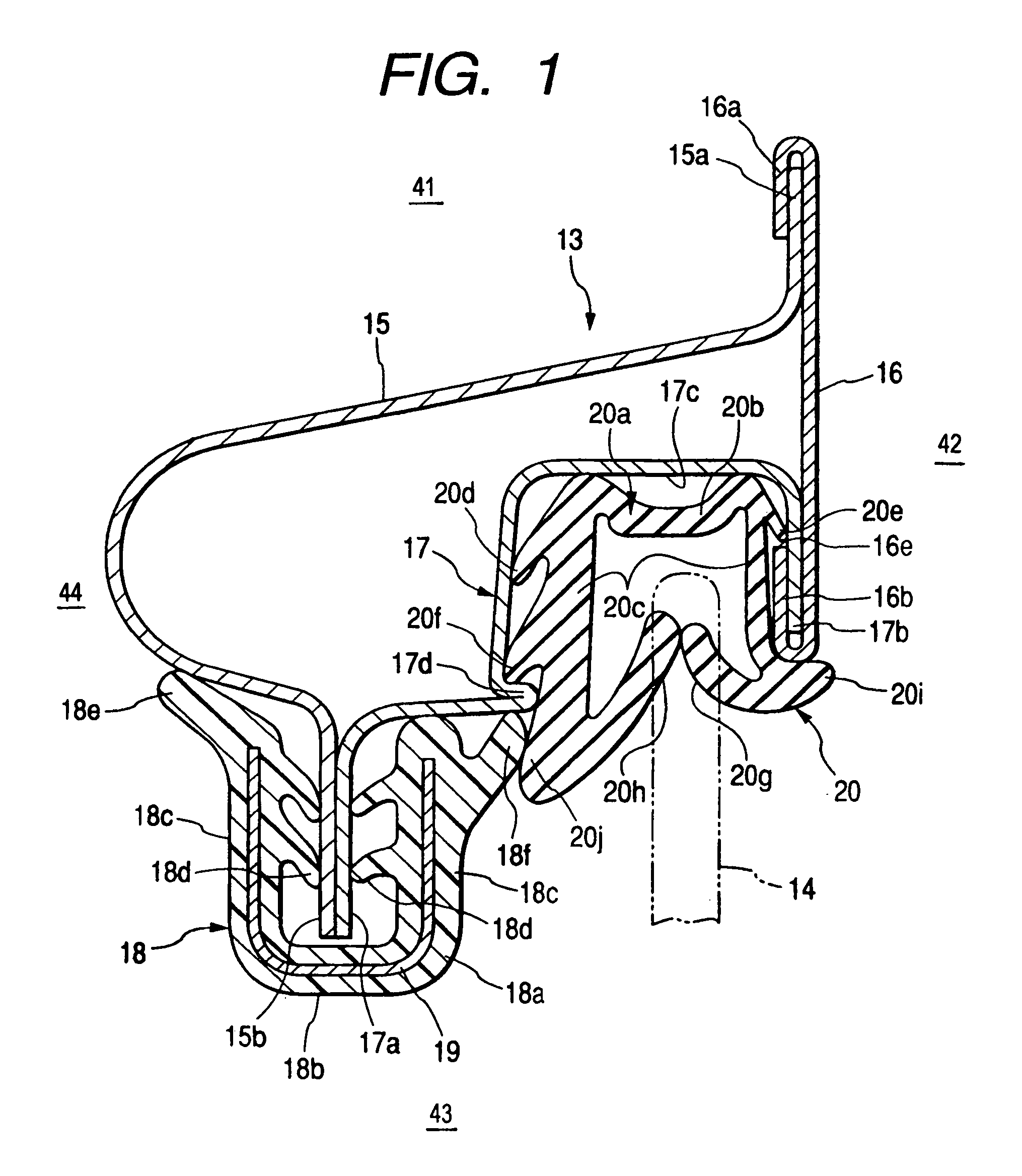
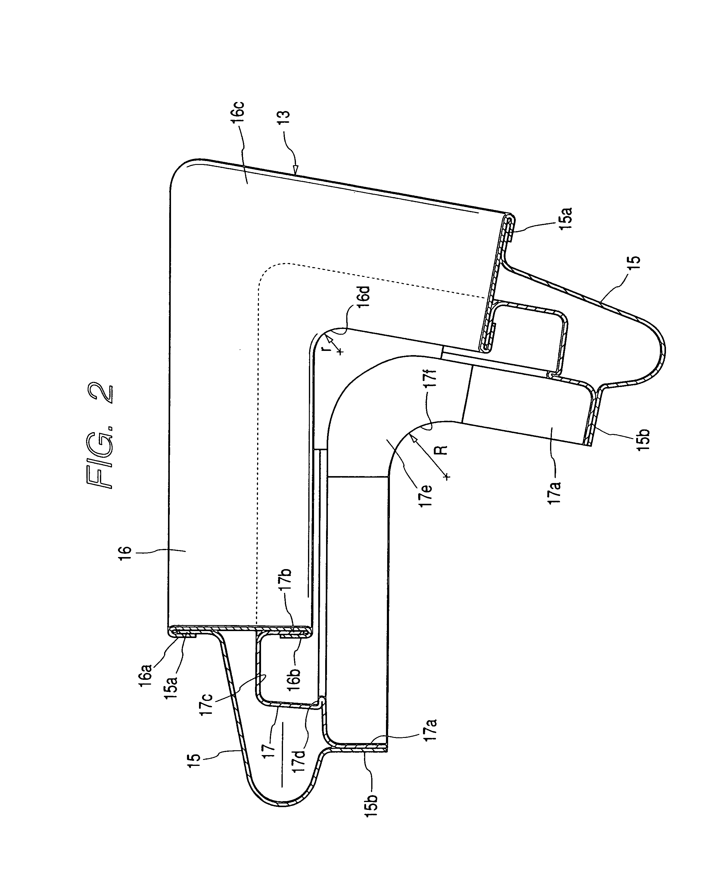
[0036]An embodiment for carrying out the present invention will be described below with reference to FIGS. 1 to 4.

[0037]As shown in FIG. 4, a side door 11 of a vehicle is constituted by a door body 12, a window frame 13 provided over the door body 12, and a door glass 14 provided up and down movably.

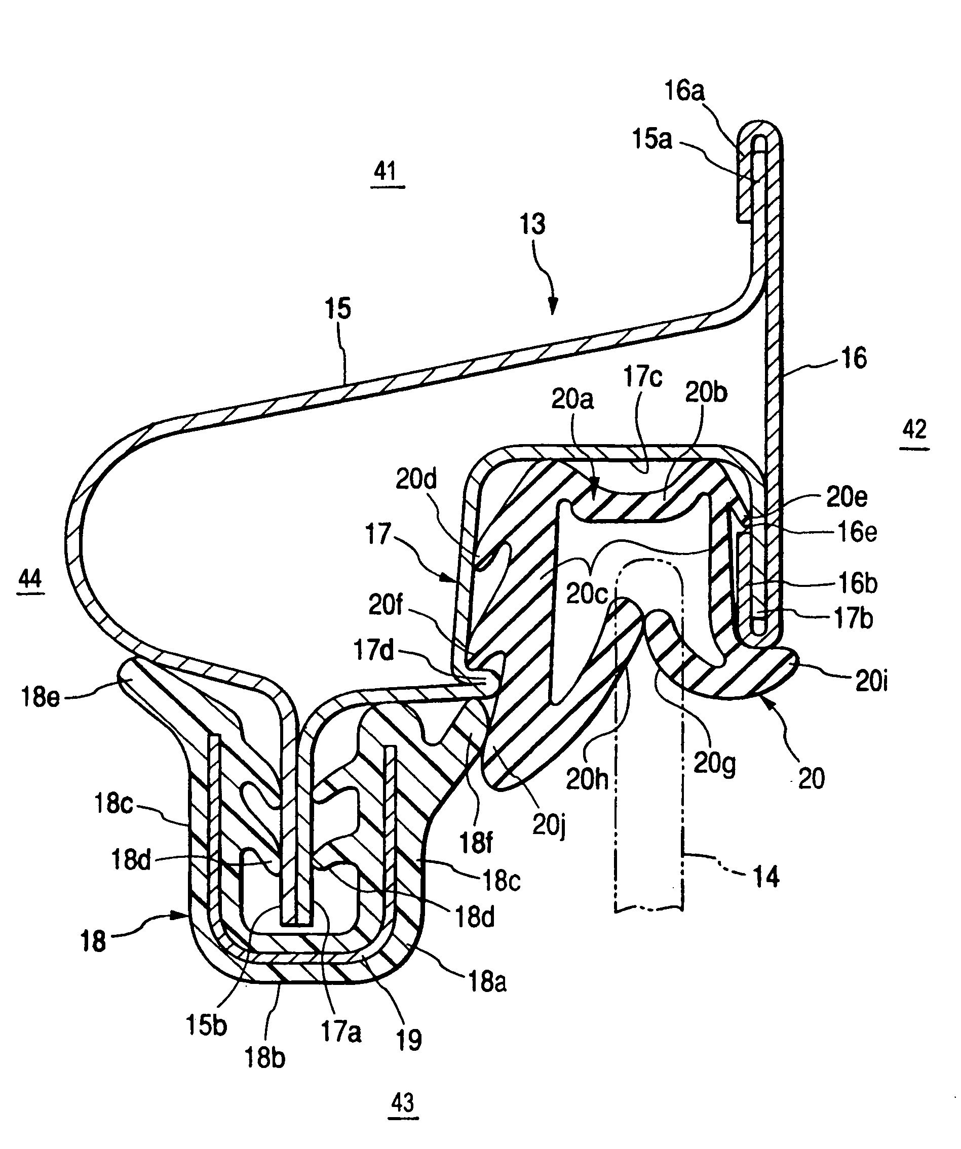
[0038]Reference numerals 41, 42, 43, and 44 indicate relative positions around the structure of FIG. 1. That is, an outer peripheral side 41, an inner peripheral side 43, a door interior side 44, and a door exterior side 42 of the structure are marked accordingly in FIG. 1. As shown in FIGS. 1 and 2, the window frame 13 is constituted by an inner panel 15, an outer panel 16 and a door sash 17 which are made of metal. An exterior flange 15a of the inner panel 15 is welded with an outer-peripheral bent portion 16a of the outer panel 16 in a condition that the inner panel 15 is fitted in the bent portion 16a. An interior flange 15b of the inner panel 15 is welded with an interior flange 17a...


PUM


Abstract

A window frame is constituted by an inner panel, an outer panel and a door sash which are formed by press molding, and a glass run body of a glass run is attached and locked in an attachment groove provided in the door sash. A trim formed separately from the glass run is attached to an interior flange of the inner panel and an interior flange of the door sash so that an exterior holding lip of the trim is brought into pressure contact with an interior holding lip provided on the glass run. A door glass is adapted to be guided to slide by seal lips of the glass run. The interior flange of the door sash and the attachment groove are integrally formed as a single component and the relative positions of these two parts are kept stable.

Description

BACKGROUND OF THE INVENTION[0001]1. Field of the Invention[0002]The present invention relates to an attachment structure for a trim and a glass run. The trim is attached to a flange formed on the inner circumference of a window frame of a vehicle, and the glass run is attached to a door sash of the window frame so that the glass run guides a door glass to make the door glass slide on the glass run when the door glass is opened and closed in a window opening of the window frame. The present application is based on Japanese Patent Application No. 2000-43189, which is incorporated herein by reference.[0003]2. Description of the Related Art[0004]In the background art, a window frame of a side door of a vehicle is constituted by an inner panel, an outer panel and a door sash which are formed by press forming. To connect these members, flanges formed on the respective members are welded with each other. It is necessary to cover those flanges with a trim having a U-shaped section. A glass ...

Claims


Application Information

Patent Timeline
Patent Type & Authority Patents(United States)
IPC IPC(8): E06B7/16B60R13/06B60J1/10
CPCB60J10/0017B60J10/04B60J10/0022B60J10/21B60J10/40B60J10/74
Inventor NOZAKI, MASAHIRO
Owner TOYODA GOSEI CO LTD
Learn More