
Sanitary napkin

Active Publication Date: 2006-06-06
UNI CHARM CORP
View PDF32 Cites 102 Cited by
  • Summary
  • Abstract
  • Description
  • Claims
  • Application Information

AI Technical Summary

Benefits of technology

[0017]The present invention has been worked out in view of the shortcomings in the prior art set forth above. It is therefore an object of the present invention to provide a sanitary napkin in which front portions of rear flaps can be firmly fixed to an undergarment as well as liquid given to leakage preventing walls can be effectively prevented from leaking out of the sanitary napkin.

Problems solved by technology

In such a front portion of the rear flap, heretofore, it has been difficult to dispose a pressure-sensitive adhesive layer for adhering the rear flap to an undergarment; in the conventional sanitary napkins, therefore, the pressure-sensitive adhesive layer has been disposed only centrally of the rear flap.
When the sanitary napkin is worn, however, central and rear portions of the sanitary napkin subjected to a tightening force of the undergarment try to fit in the cleft of the buttocks, so that the front portions of the rear flaps tend to move away from the undergarment due to deformation of liquid absorbent layer.
Furthermore, such high gathered cuffs tend to fall to cover the skin-side surface.
In this sanitary napkin, however, since four separate portions (the front wings and the fold-back portions of the rear-side wings) need be folded back against and adhered to the outer surface of the undergarment, the sanitary napkin will be troublesome to put on.
In addition, it is difficult to hold the sanitary napkin in proper position with respect to the crotch part of the undergarment until the fixing procedure is completed.
Furthermore, once the fixing procedure is completed, it will be extremely troublesome to change the position of the sanitary napkin.

Method used


Image

  • Sanitary napkin
  • Sanitary napkin
  • Sanitary napkin

Examples


first embodiment

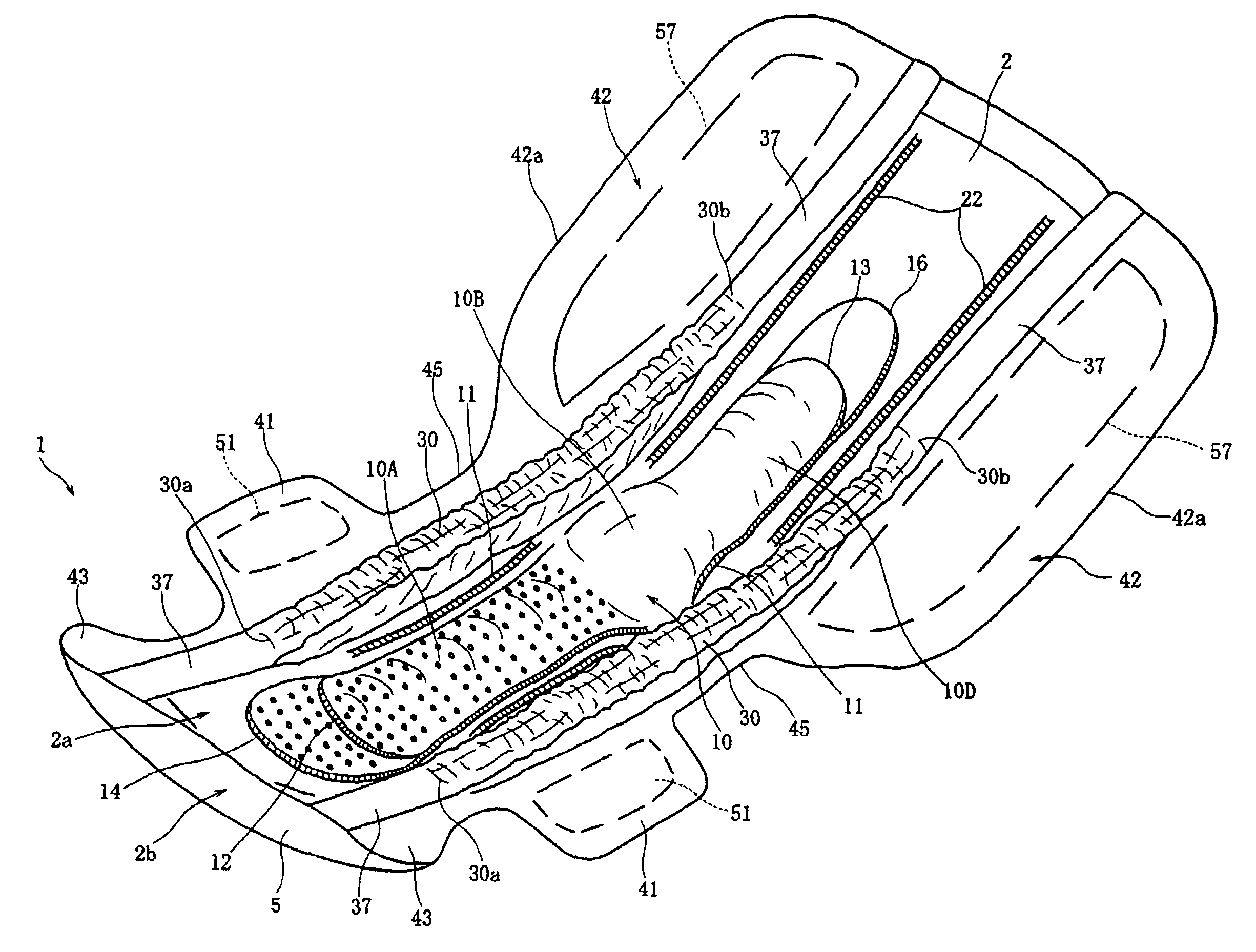
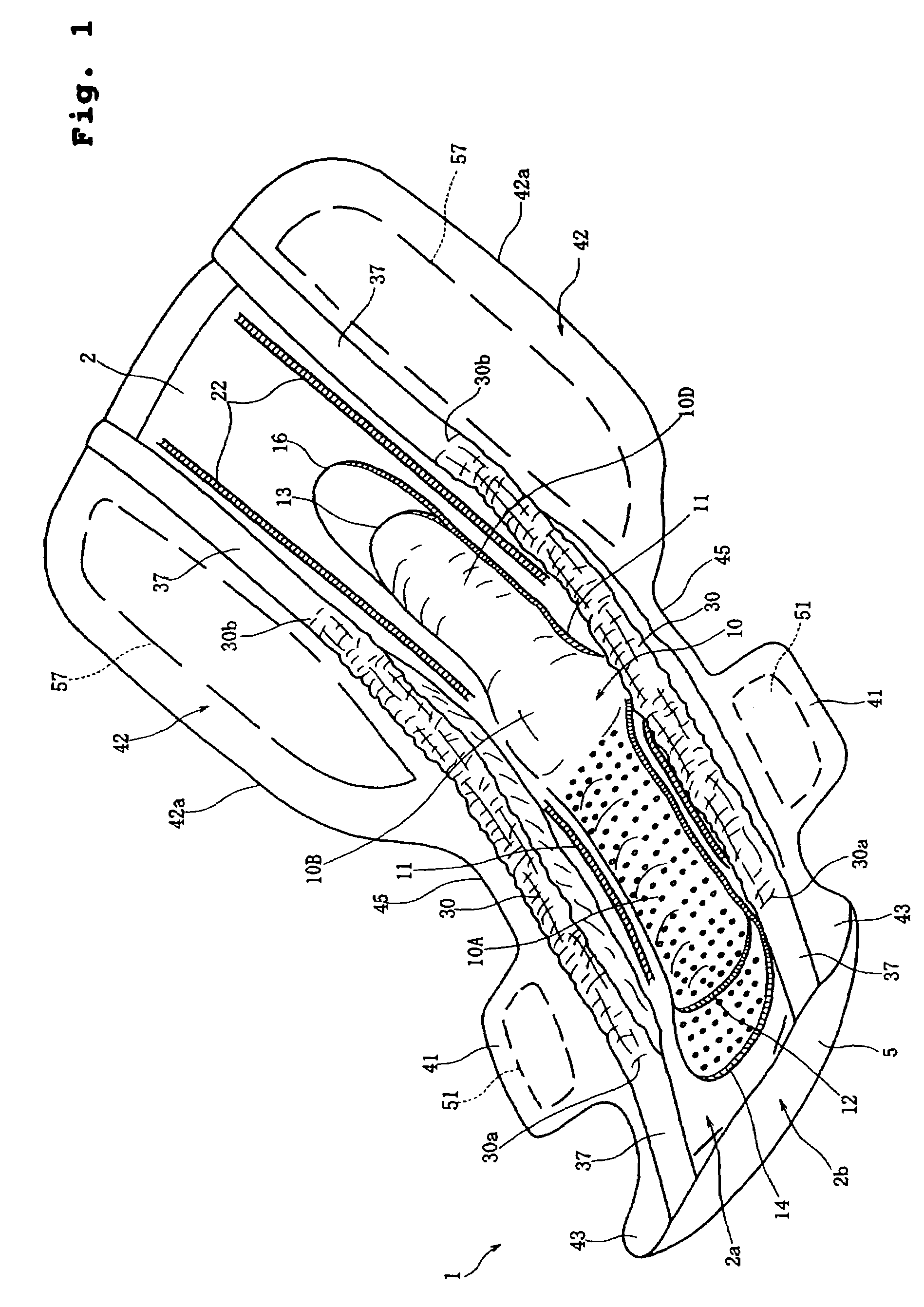
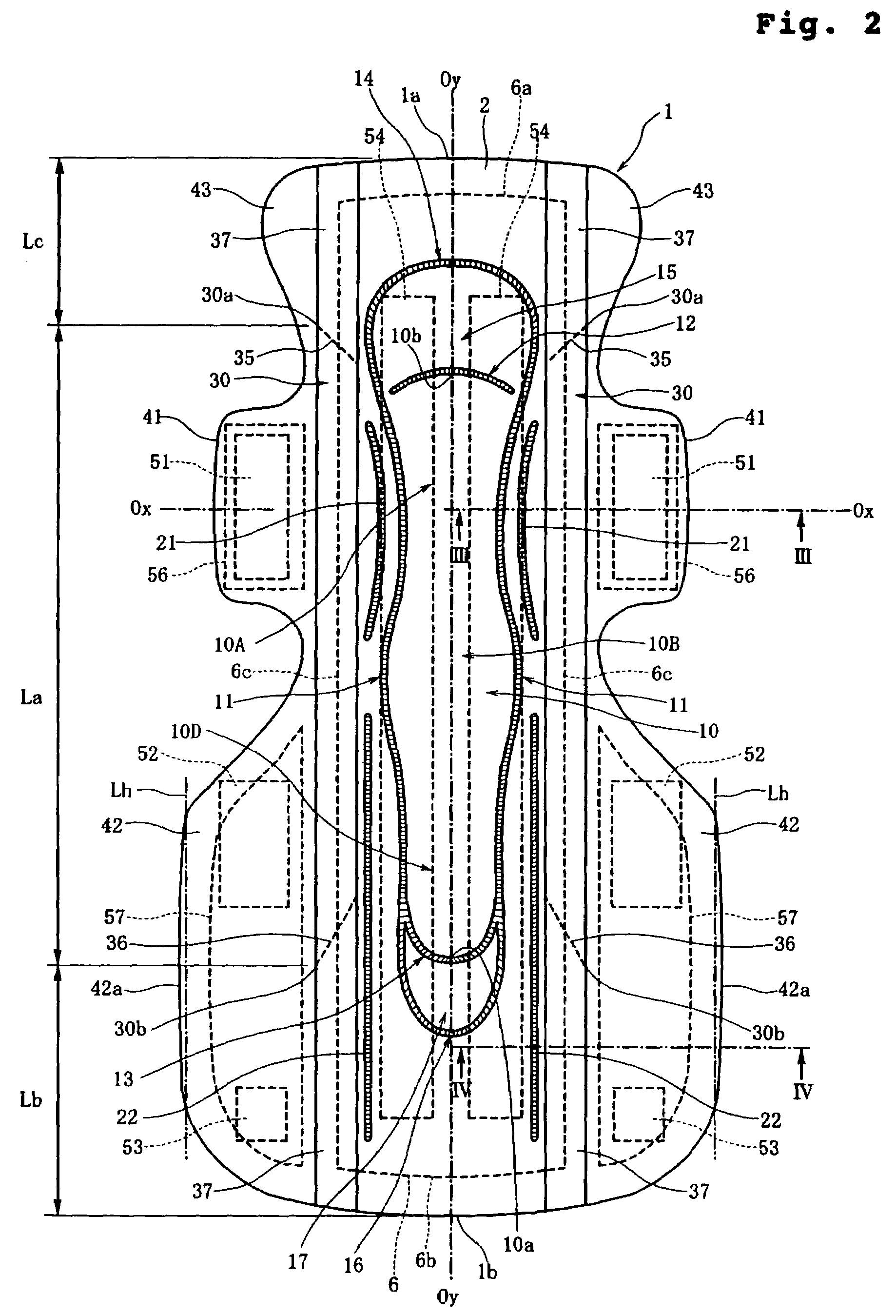
[0050]FIG. 1 is a perspective view of a sanitary napkin 1 according to the present invention; FIG. 2 is a top plan view of the sanitary napkin 1; FIG. 3 is a half sectional view taken along line III—III of FIG. 2; FIG. 4 is a half sectional view taken along line IV—IV of FIG. 2; and FIG. 5 is a top plan view for description of the shapes of flaps.

[0051]According to the first embodiment shown in FIGS. 1–5, the sanitary napkin 1 comprises: an elongated main body 2 having a skin-side surface 2a and a garment-side surface 2b; and a pair of leakage preventing walls 30, 30 that are allowed to rise from the skin-side surface 2a of the main body 2.

[0052]In FIG. 2, the sanitary napkin 1, which is slightly curved in FIG. 1, is shown in a fully opened (or flattened) state. FIG. 2 shows a longitudinal centerline Oy—Oy coinciding with midpoints of front and rear end edges 1a, 1b of the sanitary napkin 1, wherein the sanitary napkin 1 has bilateral symmetry about the longitudinal centerline Oy—Oy...

second embodiment

[0138]FIG. 7 is a top plan view showing a sanitary napkin 1A according to the present invention.

[0139]The sanitary napkin 1A is similar to the sanitary napkin 1 shown in FIG. 2, except that the pattern of the compressed grooves formed in the skin-side surface 2a is modified only partially.

[0140]The difference is such that a rear outside compressed groove 16A disposed rearward of the rear transverse compressed groove 13 is formed to connect second outside longitudinal compressed grooves 22A, 22A disposed outside thereof, as shown in FIG. 7. The remaining constructions, preferred dimensions, and preferred dimensional relationships are not changed from those in the sanitary napkin 1.

[0141]FIG. 8 is a top plan view showing a sanitary napkin 101 according to a third embodiment of the present invention. The sanitary napkin 101 has rear flaps 142 that differ from the rear flaps 42 of the first embodiment in shape. Hereinbelow, the detailed description of the portions having the same or sub...

third embodiment

[0154]FIGS. 10, 11 and 12 are bottom plan views showing modifications of the third embodiment from the garment-side. Here, the central pressure-sensitive adhesive layers 54 are omitted from the drawings.

[0155]FIG. 10 shows a sanitary napkin 101A having rear flaps 142A; FIG. 11 shows a sanitary napkin 101B having rear flaps 142B. In each napkin, the edge of the rear flap is wavy, i.e., shaped to stepwise increase the width. Here, the boundary points 147 where the rear flaps provide the widest portion are located close to the rear end edge 1b.

[0156]FIG. 12 shows a sanitary napkin 101C having rear flaps 142C, wherein the boundary points 147 are located rearward of the rear end edge 1b. Therefore, when the sanitary napkin 101C is fixed on the inner surface of the undergarment, the boundary points 147 can easily be pulled obliquely upward.

[0157]According to the present invention, as has been described hereinabove, the rear flaps can be firmly fixed to an inner surface of an undergarment...


PUM


Abstract

Disclosed is a sanitary napkin which is effective in preventing liquid from leaking out obliquely rearward. The sanitary napkin has rear flaps rearward of fold-back flaps to be wrapped around a crotch part of an undergarment. The rear flap has a side edge substantially parallel to a longitudinal centerline. The rear flap is provided at its front portion with a rear pressure-sensitive adhesive layer. The rear pressure-sensitive adhesive layer is disposed forward of a rear end of a leakage preventing wall and a rear end of a main absorbent region. Since the rear flaps can be firmly fixed through the rear pressure-sensitive adhesive layers, the leakage preventing walls hardly move, so that the leakage preventing walls, as well as the rear flaps outside them, can effectively prevent obliquely rearward leakage.

Description

BACKGROUND OF THE INVENTION[0001]1. Field of the Invention[0002]The present invention relates to a sanitary napkin suitable for nighttime use. More particularly, the invention relates to a sanitary napkin provided with rear flaps for widely covering a posterior part of the crotch and the buttocks.[0003]2. Description of the Related Art[0004]Sanitary napkins suitable for nighttime use are typically constructed to include an elongated main body and front fold-back flaps and rear flaps projecting outward from transversely opposite sides of the main body.[0005]Japanese Unexamined Patent Publication No. 2001-95842 (Patent Publication 1) discloses a sanitary napkin, wherein a narrowest portion where the width of the napkin is smallest is disposed rearward of the fold-back flaps but forward of the rear flaps. The rear flaps are shaped such that the width of the napkin gradually increases rearward from the narrowest portion, reaches a widest portion, and gradually decreases from the widest ...

Claims


Application Information

Patent Timeline
IPC IPC(8): A61F13/20A61F5/44A61F13/15A61F13/472A61F13/56
CPCA61F13/4753A61F13/5616A61F13/476A61F2013/4706
Inventor KINOSHITA, MASATAKANISHITANI, KAZUYATANIO, TOSHIYUKISAKAI, AKANEKUDO, JUN
Owner UNI CHARM CORP
Learn More