Cable assembly for electrosurgical pencil

a cable and pencil technology, applied in the direction of power cables, cables, coupling device connections, etc., can solve the problems of affecting the safety of patients during operation, rigid and heavy, and the general use cable will be more expensive, so as to reduce the risk of injury, and improve the safety of patients

Inactive Publication Date: 2006-06-06
FUNG ALEX +1
View PDF8 Cites 17 Cited by
  • Summary
  • Abstract
  • Description
  • Claims
  • Application Information

AI Technical Summary

Benefits of technology

[0006]An object of this invention is to provide a cable assembly for an electrosurgical pencil which overcomes certain prior art deficiencies such that, in comparison to certain conventional cable assemblies, the cable assembly of this invention is cheaper in cost, lighter in weight, thinner in outside diameter, more flexible in total length, and / or provides a more stable plug-socket connection.
[0007]For achieving the above mentioned object, the cable assembly of this invention comprises a power and signal transmitting multiple-core cable with an attachment plug, in which the power transmitting core has more conductors and thicker insulation than two signal transmitting cores. The attachment plug has plastic plug-pins with spring-steel strips, or has metal plug-pins with recesses on the plug body near the plug-pins, for increasing the flexibility to any loose or tight socket in mating.

Problems solved by technology

The general-use cable will be more expensive, rigid and heavy than the Safety Standard (AAMI) required.
If the contact between the plug and the socket is unstable and the signal transmitting is interrupted, though there is no safety problem to the device, there may be a terrible safety problem to the patient during the operation.
Therefore, the traditional attachment plug is not ideal to use in different electrosurgical generators.
Simply speaking, the attachment plug used for power transmitting can not meet the requirement of transmitting stable signals.
Furthermore, if the plug-pins are too loose to plug in, they will easily pull out during the operation.
If they are too hard to plug in, they will be too difficult to use.

Method used


Image

  • Cable assembly for electrosurgical pencil
  • Cable assembly for electrosurgical pencil
  • Cable assembly for electrosurgical pencil

Examples


Embodiment Construction

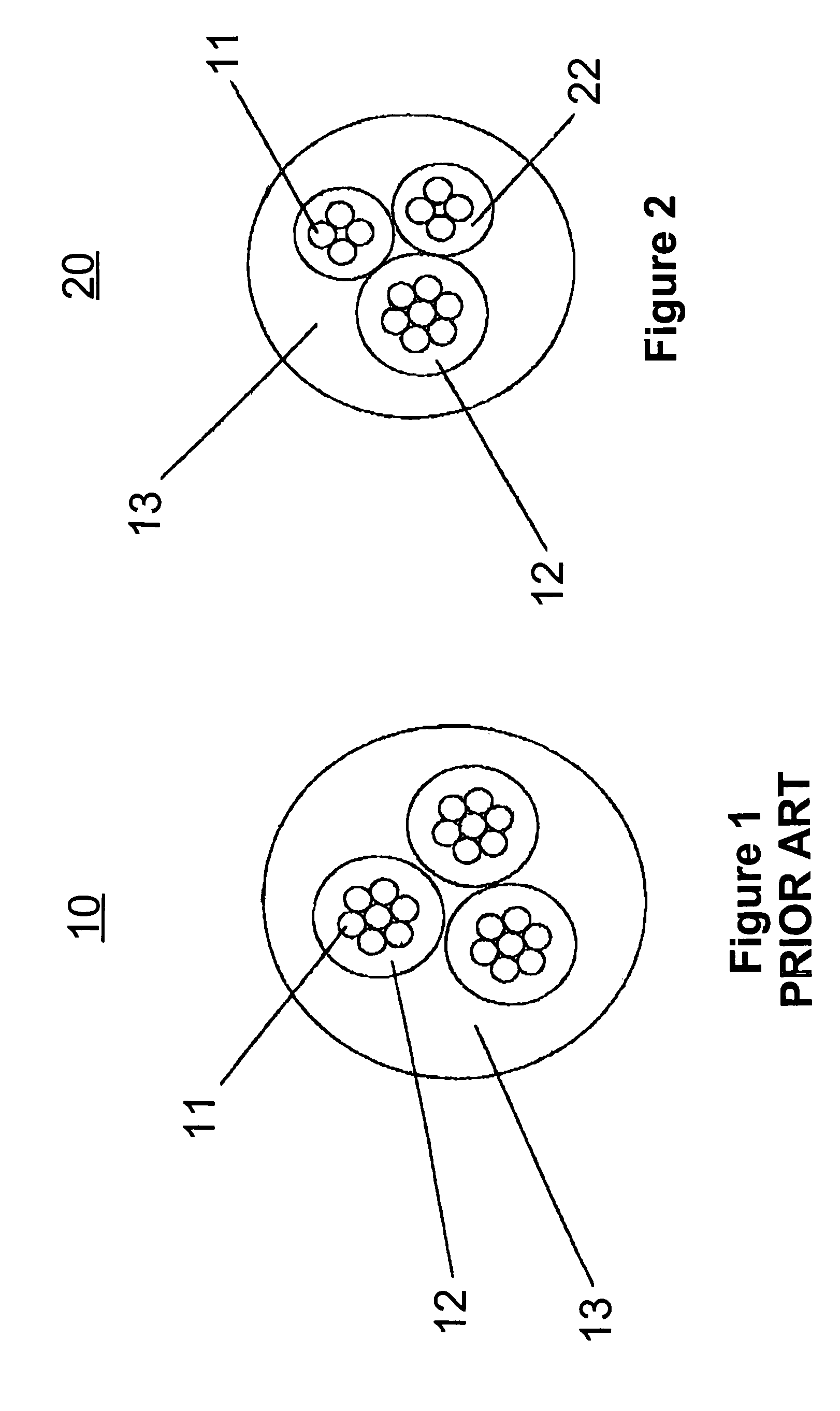
[0017]FIG. 1 is a section view of a prior art general-use power transmitting cable 10. There are three cores in the cable 10. Each core includes a strand of 7 conductors 11 and an insulation coat 12. An outer sleeve 13 encloses the three cores to form an integrated cable 10. Since in safety testing, each core must be tested under same the ampere / voltage / wattage rating, the three cores must have the same construction. This will reduce the flexibility of the cable in operation.

[0018]FIG. 2 is a section view of the cable of this invention. In FIG. 2, the cable of this invention is designated by the numeral 20. In cable 20 there still are three cores. The core used for transmitting power is substantially the same one shown in FIG. 1. For the other two cores, since they are used to transmit signals, the number of conductors is reduced to 4. Thus, the total number of the conductors in a given cable is reduced to 15. It is almost a 50% reduction in comparison to FIG. 1. Because in FIG. 2, ...


PUM

PropertyMeasurementUnit
diameteraaaaaaaaaa
flexibilityaaaaaaaaaa
diameteraaaaaaaaaa

Abstract

A cable assembly for an electrosurgical pencil comprises a power and signal transmitting multiple-core cable with an attachment plug, in which the power transmitting core has more conductors and thicker insulation than the two signal transmitting cores. The attachment plug has plastic plug-pins with spring-steel strips, or has metal plug-pins with recesses on the plug body near the plug-pins, to increase the flexibility to mate with any loose or tight socket. The cable assembly of this invention is cheaper in cost, lighter in weight, thinner in outside diameter, more flexible in total length and provides a more stable plug-socket connection.

Description

FIELD OF THE INVENTION[0001]This invention relates to a cable assembly, particularly to a cable assembly used for an electrosurgical pencil.BACKGROUND OF THE INVENTION[0002]The cable assembly used for an electrosurgical pencil includes a cable and a attachment plug. Until now, all manufacturers of electrosurgical pencils have paid little attention to the cable assembly. They typically have purchased existing traditional general-use three-core cables with an existing attachment plug to equip their electrosurgical pencils.[0003]As for the cable, a three-core cable for general-use must have three cores in the same conductor diameter and same insulation, while in an electrosurgical pencil, only one core is used for transmitting heavy power and the other two are only used for transmitting signals. Therefore, the conductor diameter and insulation of the other two cores can be greatly reduced. To do so, not only the cost can be reduced, but also the operational function of the cable can be...

Claims


Application Information

Patent Timeline
Patent Type & Authority Patents(United States)
IPC IPC(8): H02G15/02A61B18/14H01B9/00H01B11/02H01R13/52
CPCH01R13/5224H01B9/003A61B2018/00178H01R2201/12
Inventor FUNG, ALEXFUNG, KIPSON
Owner FUNG ALEX
Why Eureka
Try Eureka