Apparatus for controlling temperature profiles in liquid droplet ejectors

a technology of temperature profiles and ejectors, applied in electrical apparatus, ohmic-resistance heating, printing, etc., can solve problems such as creating design problems of their own, and paths of current within a conductor also producing non-uniform heating profiles

Inactive Publication Date: 2006-06-06
EASTMAN KODAK CO
View PDF15 Cites 4 Cited by
  • Summary
  • Abstract
  • Description
  • Claims
  • Application Information

AI Technical Summary

Problems solved by technology

Since it is desirable to shape heater resistors to better control the quality and trajectory of the ejected droplet, these shapes can also create design issues of their own.
This being understood, the two paths of current within a conductor will also produce a non-uniform heating profile due to the non-uniform current flow.

Method used


Image

  • Apparatus for controlling temperature profiles in liquid droplet ejectors
  • Apparatus for controlling temperature profiles in liquid droplet ejectors
  • Apparatus for controlling temperature profiles in liquid droplet ejectors

Examples


Embodiment Construction

[0019]The present description will be directed in particular to elements forming part of, or cooperating more directly with, apparatus in accordance with the present invention. It is to be understood that elements not specifically shown or described may take various forms well known to those skilled in the art. In the following description and drawings, identical reference numerals have been used, where possible, to designate elements common to the figures.

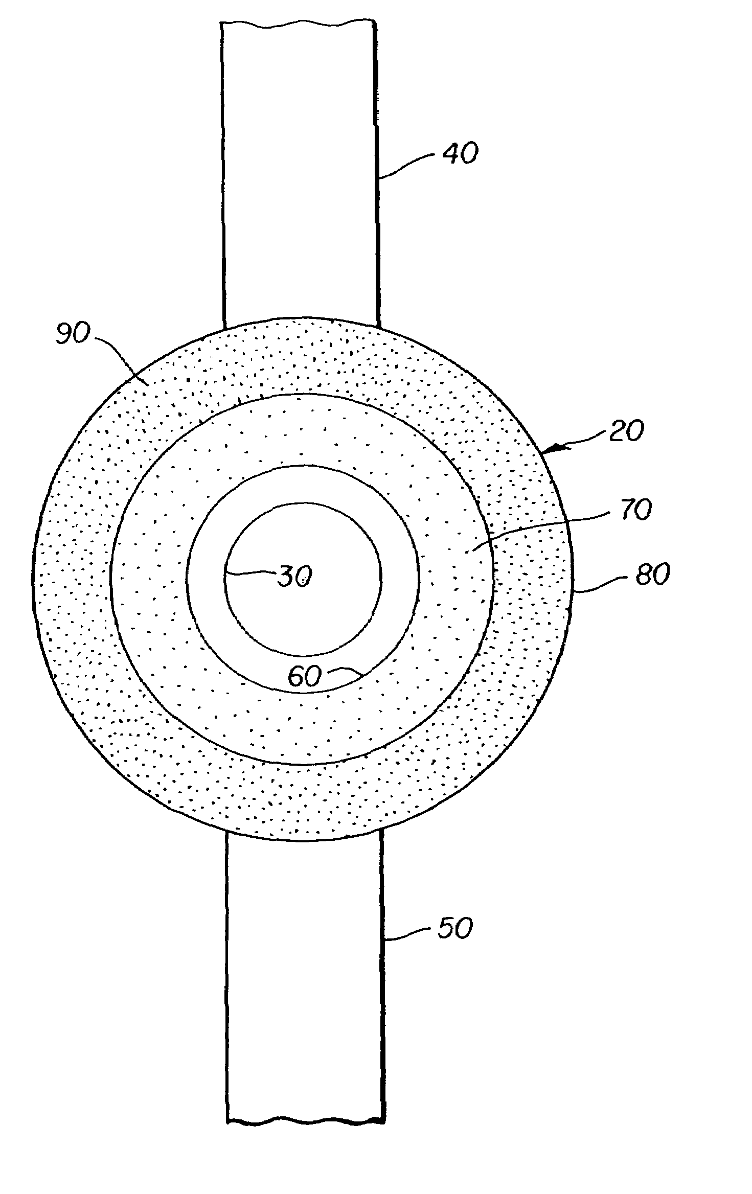
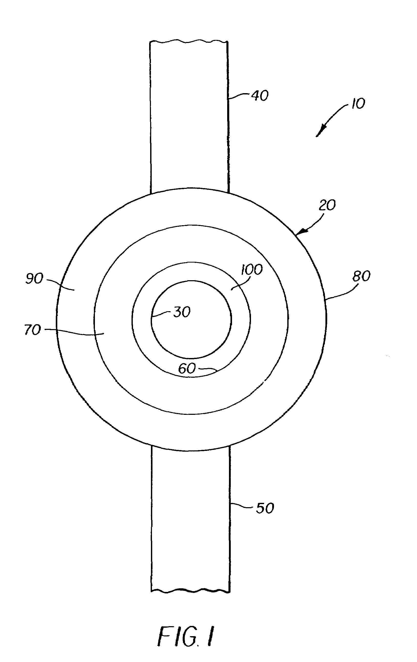
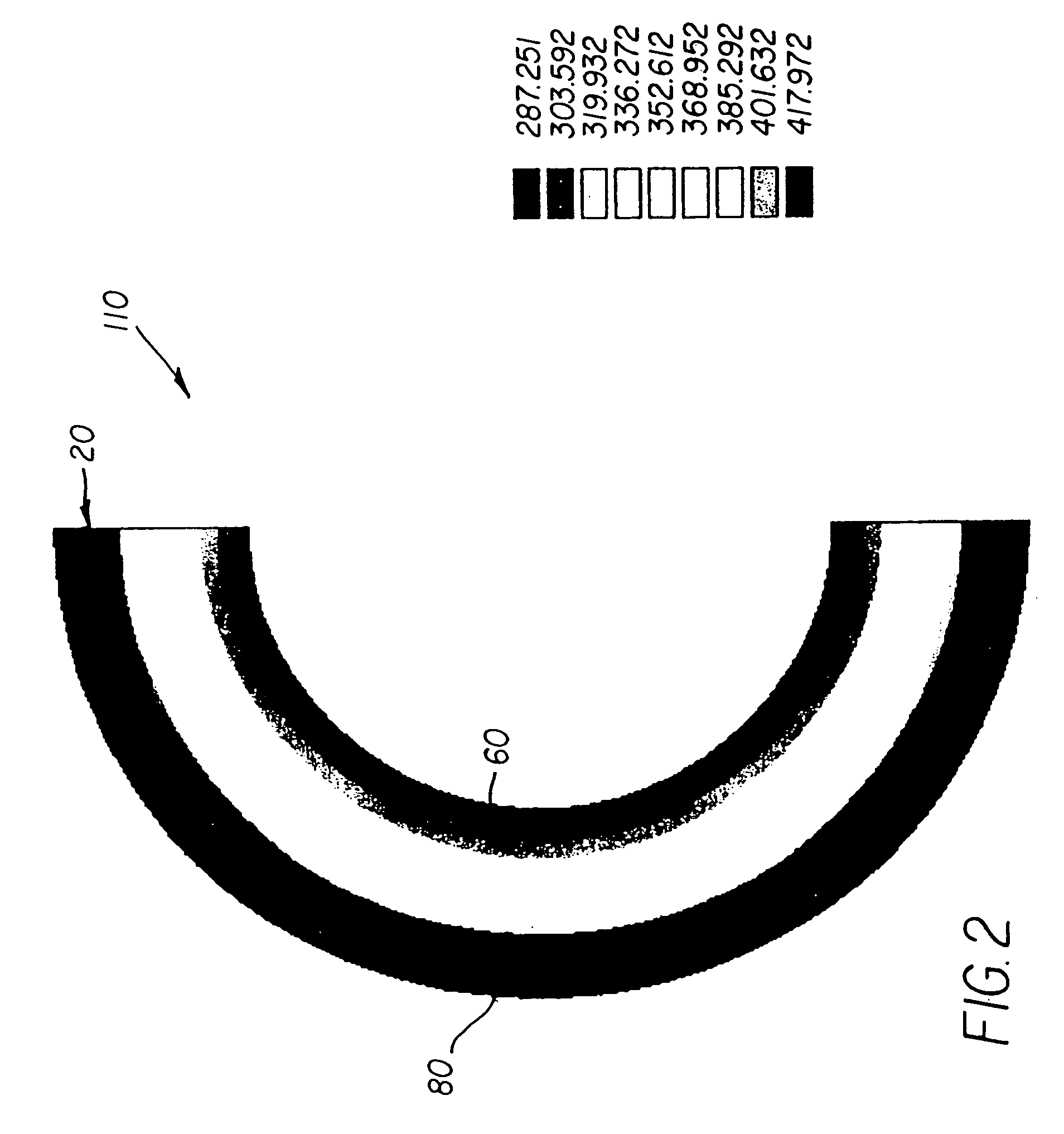
[0020]Referring to FIG. 1, drawn is a two dimensional view of the substrate of an orifice plate 10 upon which is disposed an inkjet heater 20 which is arranged about an ejection nozzle 30. An electrical input conductor 40 and an electrical output conductor 50 supply electrical current to the inkjet heater 20. The circular or ring-like construction of the inkjet heater 20 by its physical nature allows a shorter current path around the inside path 60 versus the outside path 80 of the inkjet heater 20. Also shown for means of clarifi...


PUM


Abstract

A heater is provided. The heater includes a first material having a circular form and a first sheet resistively. The first material has a first radius of curvature. The heater also includes a second material having a circular form and a second sheet resistively. The second material is positioned adjacent to the first material and has a second radius of curvature. The first radius of curvature is greater than the second radius of curvature and the first sheet resistively is less than the second sheet resistively.

Description

FIELD OF THE INVENTION[0001]The invention relates generally to the field of liquid droplet ejection, for example, inkjet printing, and more specifically to an apparatus for controlling temperature profiles in liquid droplet ejection mechanisms.BACKGROUND OF THE INVENTION[0002]The state of the art of inkjet printing, as one type of liquid droplet ejection, is relatively well developed. A wide variety of inkjet printing apparatus are available for commercial purchase from consumer desktop printers that produce general documents to commercial wide format printers that produce huge photographic quality posters.[0003]A thermal inkjet printer typically comprises a transitionally reciprocating printhead that is fed by a source of ink to produce an image-wise pattern upon some type of receiver. Such printheads are comprised of an array of nozzles through which droplets of ink are ejected by the rapid heating of a volume of ink that resides in a chamber behind a given nozzle. This heating is...

Claims


Application Information

Patent Timeline
Patent Type & Authority Patents(United States)
IPC IPC(8): H05B1/00B41J2/05B41J2/14B41J2/345
CPCB41J2/14056B41J2/14137B41J2/14129B41J2/1412
Inventor LOPEZ, ALIDELAMETTER, CHRISTOPHER N.STEPHANY, THOMAS M.HAWKINS, GILBERT A.
Owner EASTMAN KODAK CO
Why Eureka
Try Eureka