IC module assembly

a technology of modules and modules, applied in the field of ic module assemblies, to achieve the effect of reducing manufacturing costs, reducing manufacturing steps, and facilitating soldering steps

Active Publication Date: 2006-06-06
JU TED
View PDF6 Cites 13 Cited by
  • Summary
  • Abstract
  • Description
  • Claims
  • Application Information

AI Technical Summary

Benefits of technology

[0007]The secondary object of the invention is therefore to specify an IC module assembly that can omit an IC socket to cut down costs and manufacturing steps.
[0008]The third object of the invention is therefore to specify an IC module assembly that provides easy soldering steps for connection between the IC module and resilient members, the manufacturing costs is further saved.

Problems solved by technology

However, as the tendency for increasing the quantity of the pins needs to meet, the pin type IC package meet requirements no more and a pad type IC package is consequently used.

Method used


Image

  • IC module assembly
  • IC module assembly
  • IC module assembly

Examples


Embodiment Construction

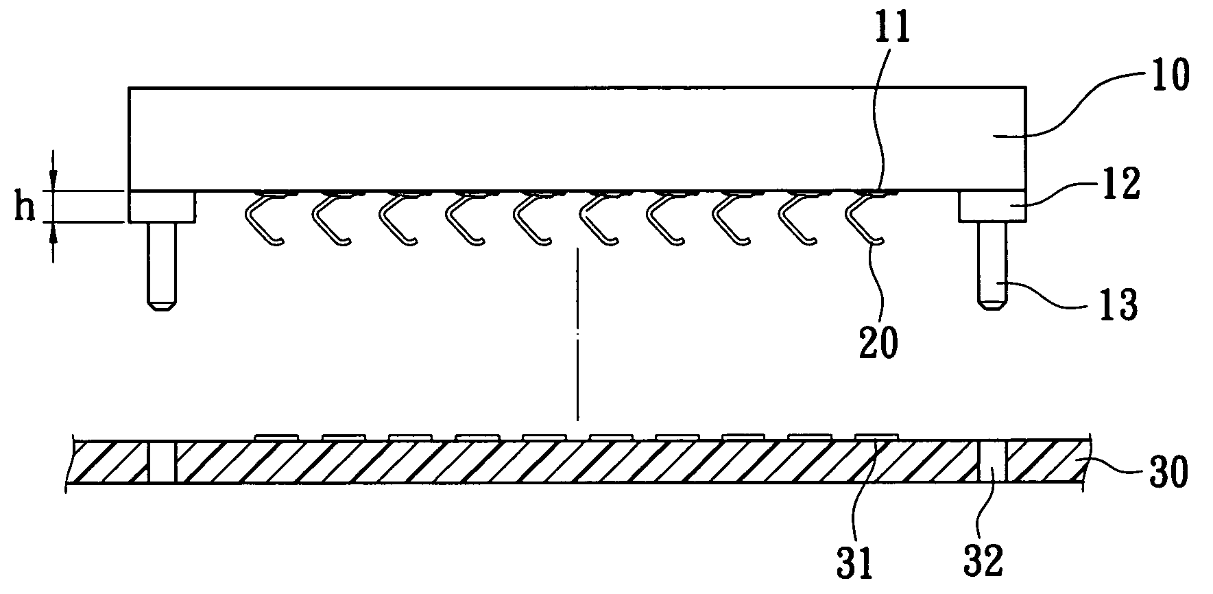
[0022]With respect to FIG. 4, an IC module assembly includes an IC module 10 having a plurality of pads 11 disposed on a bottom thereof, a plurality of resilient members 20 respectively soldering to the pads 11, and a PCB 30 having a plurality of conductive patterns 31 arranged on a top thereof and corresponding to the resilient members 20 respectively, whereby the IC module 10 electrically connects the PCB 30 by the resilient members 20 abutting against the conductive patterns 31 of the PCB 30 and soldering to the pads 11 of the IC module 10. An IC socket receiving the IC module assemble can be omitted to cut down costs and manufacturing steps accordingly, and easy soldering steps for connection between the IC module 10 and resilient members 20 can be provided thereby. The IC module 10 includes a limit portion 12 extending from the bottom thereof, and an orientation post 13 disposed on the bottom thereof. The limit portion 12 has a predetermined height “h” to avoid over compressing...


PUM


Abstract

An IC module assembly includes an IC module including a plurality of pads disposed on a bottom thereof, a plurality of resilient members respectively soldering to the pads, and a PCB having a plurality of conductive patterns arranged on a top thereof and corresponding to the resilient members respectively, whereby the IC module electrically connects the PCB by the resilient members abutting against the conductive patterns of the PCB.

Description

BACKGROUND OF THE INVENTION[0001]1. Field of the Invention[0002]The present invention relates to an IC module assembly, and particularly relates to an IC module assembly adopted for an IC module having a plurality of pads disposed thereon.[0003]2. Background of the Invention[0004]FIG. 1 shows a first connectional IC module 10a having a housing 11a, a plurality of pins (not shown) received in the housing 11a, and a plurality of solder balls 12a arranged corresponding to the pins and exposing out of the housing 11a. The first conventional IC module 10a is so-called Ball Grid Array (BGA) IC package, and applied to a first connectional IC socket (not shown) that has a plurality of patterns relating to the solder balls 12a. With respect to FIG. 2, a second conational IC module 20a having a housing 21a, and a plurality of pins 22a extending from the housing 21a. The pins 22a can mate with an IC socket (not shown) or solder into a through-hole printed circuit board (PCB). However, as the t...

Claims


Application Information

Patent Timeline
Patent Type & Authority Patents(United States)
IPC IPC(8): H01L23/48H01L23/52H01L29/40H01L23/495H01L23/498H05K3/32
CPCH01L23/49811H05K3/325H01L24/72H01L2924/14H05K2201/10946H05K2201/0311H05K2201/10719
Inventor JU, TED
Owner JU TED
Why Eureka
Try Eureka