Digital DLL apparatus for correcting duty cycle and method thereof

a technology of digital dll and duty cycle, applied in pulse manipulation, pulse technique, instruments, etc., can solve the problems of time delay and conventional dlls cannot correct phase delay

Active Publication Date: 2006-06-06
SK HYNIX INC
View PDF22 Cites 52 Cited by
  • Summary
  • Abstract
  • Description
  • Claims
  • Application Information

AI Technical Summary

Problems solved by technology

However, certain elements of a semiconductor device results in a timing delay.
However, their conventional DLLs cannot correct a phase delay caused by a duty error when data of external clock signal is processing, wherein the duty error is difference between real duty cycle and 50% duty cycle and it may be occurred during processing the external clock.

Method used


Image

  • Digital DLL apparatus for correcting duty cycle and method thereof
  • Digital DLL apparatus for correcting duty cycle and method thereof
  • Digital DLL apparatus for correcting duty cycle and method thereof

Examples


Embodiment Construction

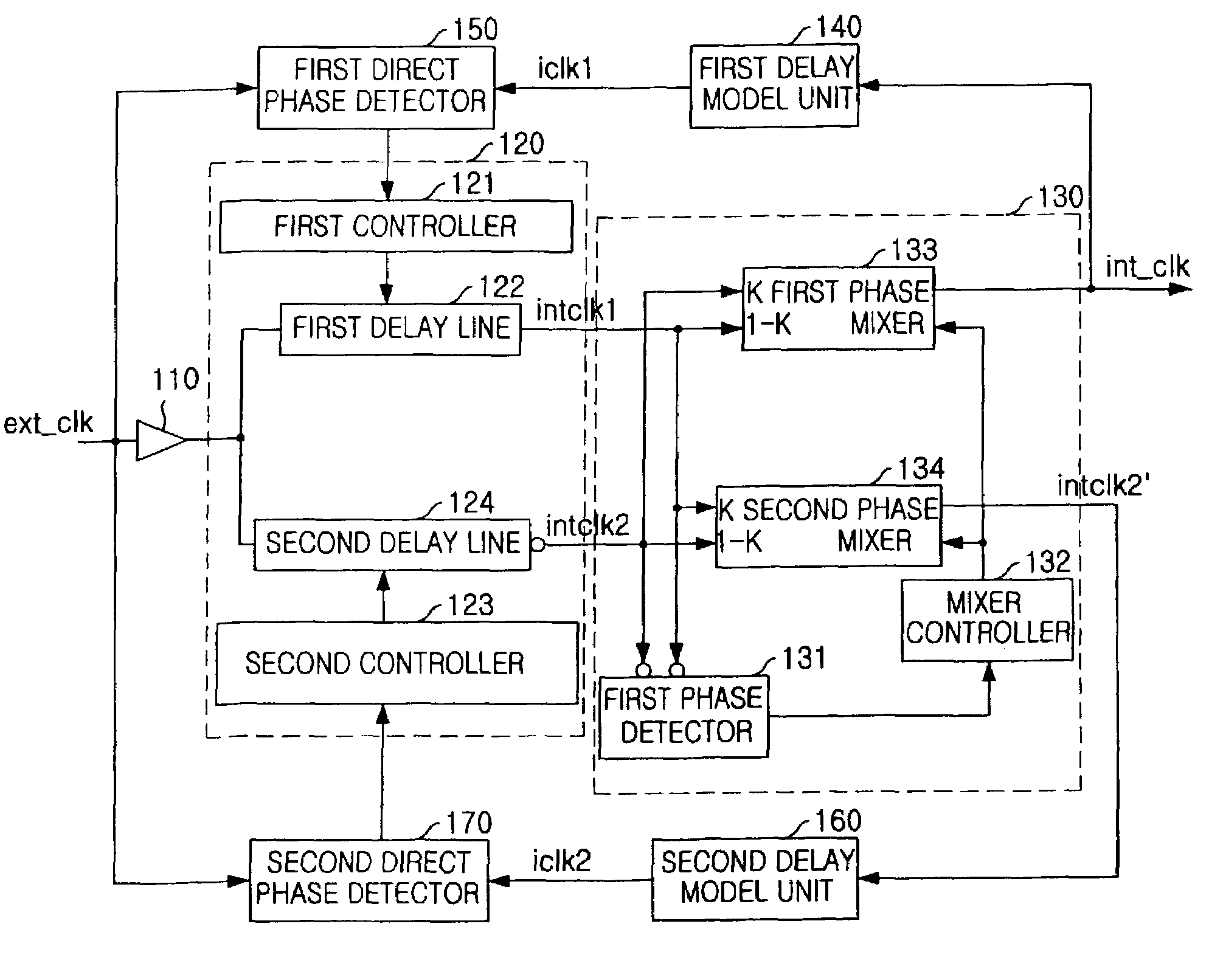
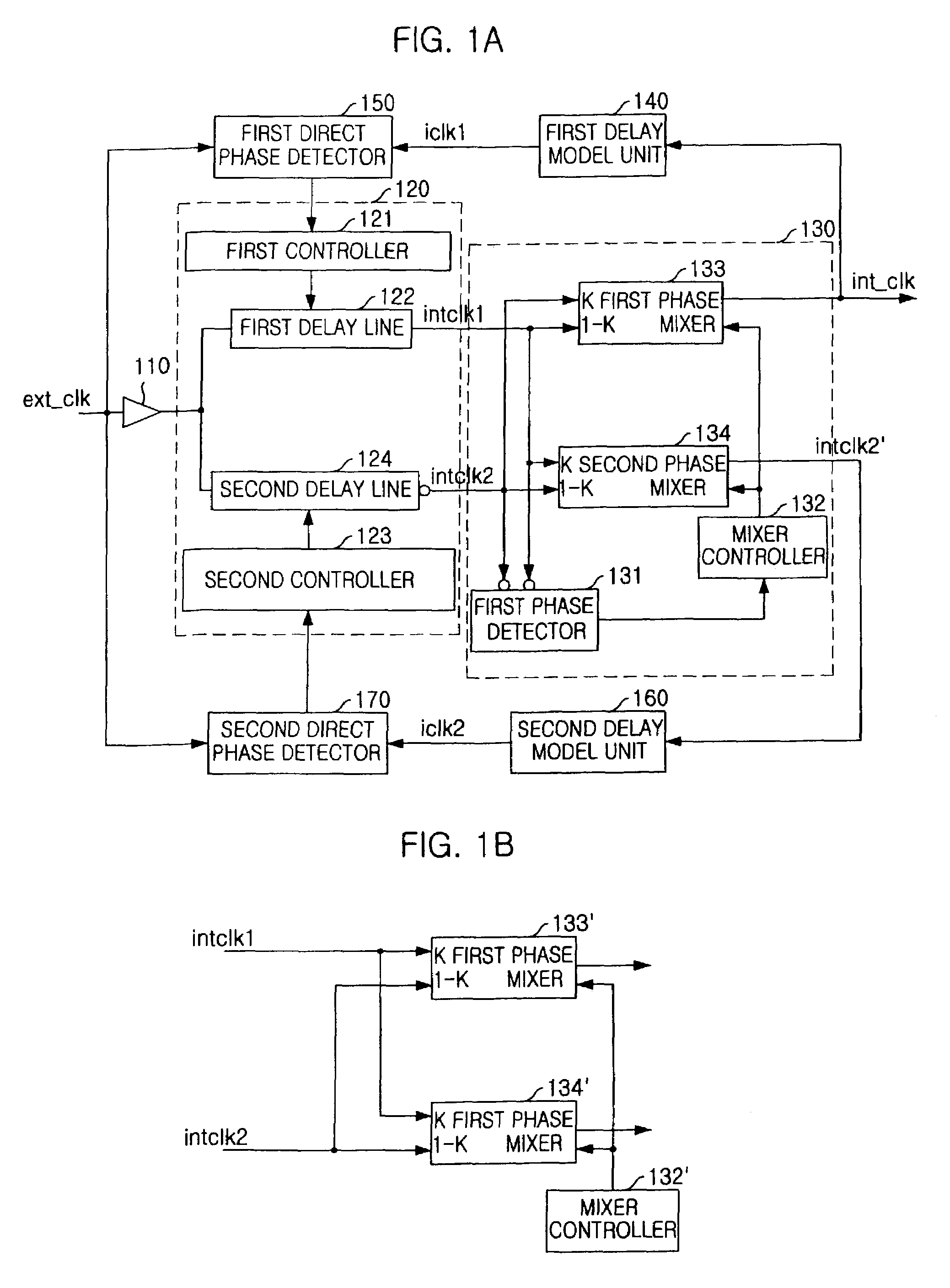
[0024]FIG. 1A is a block diagram showing a digital DLL apparatus for correcting a duty cycle in accordance with a preferred embodiment. The digital DLL apparatus includes a buffer 110, a delay line unit 120, a duty error controller 130, a first delay model unit 140, a first direct phase detector 150, a second delay model unit 160 and a second direct phase detector 170.

[0025]The buffer 110 receives an external clock signal (ext_clk) and generates a first internal clock signal which becomes activated at an edge of a clock. The first internal clock signal is inputted to the delay line unit 120.

[0026]The delay line unit 120 receives the first internal clock signal and also receives a first and second detection signals from the first and second direct phase detector 150 and 170. The delay line unit 120 delays the first internal clock signal based on the first and second detection signals and outputs a first delay internal clock signal (intclk1) and a second delayed internal clock signal ...


PUM


Abstract

A digital DLL apparatus and a method for correcting a duty cycle are disclosed. The apparatus includes: a delay line unit for receiving external clock signal and generating first and second delayed internal clock signals by delaying the external clock signal; a duty error controller for receiving the first and second delayed clock signals and outputting a first duty controlled clock signal and second duty controlled clock signal by shifting edges of the first and second delayed internal clock signals; and a delay model unit for compensating a delay of the duty controlled clock signal by estimating a delay amount of system. The present invention can correct the duty error by using the phase mixer and generate an internal clock signal having 50% of duty cycle.

Description

TECHNICAL FIELD[0001]A digital delay locked loop DLL circuitry and a method for correcting a duty cycle are disclosed. More particularly, a digital DLL apparatus and a method for correcting a duty cycle are disclosed which are used in a semiconductor or a computer system which needs a clock generator for compensating a skew between an external clock and internal clock.DESCRIPTION OF RELATED ART[0002]A delay locked loop (DLL) is widely used in a synchronous random access memory (RAM) for synchronization an external clock signal and an internal clock signal. In the synchronous RAM, all operations such as write or read are supposed to be operated at a rising edge. However, certain elements of a semiconductor device results in a timing delay. For synchronizing operation timing at the rising edge in the synchronous RAM, the timing delay must be eliminated. The delay locked loop (DLL) circuit receives the external clock signal and generates the internal clock signal for synchronizing two ...

Claims


Application Information

Patent Timeline
Patent Type & Authority Patents(United States)
IPC IPC(8): H03L7/06H03K5/00G11C7/22G11C11/407H03D3/24H03L7/07H03L7/081H03L7/087H04L7/02
CPCH03L7/087H03L7/0814H03L7/07H03K2005/00039H03L7/0816G11C11/407
Inventor KWAK, JONG-TAE
Owner SK HYNIX INC
Why Eureka
Try Eureka