Dual-band antenna for a wireless local area network device

a wireless local area network and dual-band technology, applied in the direction of elongated active element feed, resonant antenna, radiating element structure, etc., can solve the problem of sensitive size and weight of stations

Active Publication Date: 2006-06-06
AVAGO TECH INT SALES PTE LTD
View PDF27 Cites 96 Cited by
  • Summary
  • Abstract
  • Description
  • Claims
  • Application Information

AI Technical Summary

Problems solved by technology

Such stations are, howev...

Method used


Image

  • Dual-band antenna for a wireless local area network device
  • Dual-band antenna for a wireless local area network device
  • Dual-band antenna for a wireless local area network device

Examples


Embodiment Construction

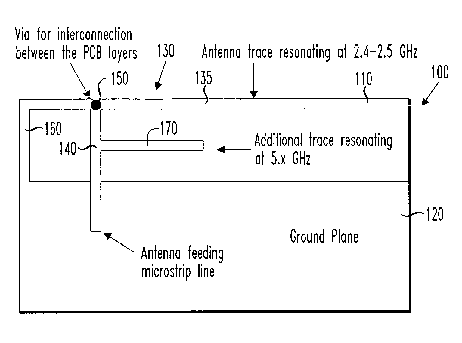
[0021]Referring initially to FIG. 1, illustrated is a plan view of a first embodiment of a dual-band antenna constructed according to the principles of the present invention.

[0022]The dual-band antenna, generally designated 100, is supported by a substrate 110. The substrate 110 can be any suitable material. If cost is less of an object, the substrate 110 can be composed of a low-loss material (i.e., a material that does not significantly attenuate proximate electromagnetic fields, including those produced by the dual-band antenna 100). If cost is more of an object, the substrate 110 can be formed from a more conventional higher loss, or “lossy,” material such as FR-4 PCB, which is composed of fiberglass and epoxy. However, as Wielsma, supra, describes, such “lossy” materials can compromise antenna range by absorbing energy that would otherwise contribute to the electromagnetic field produced by the dual-band antenna 100. Wielsma teaches that antenna range can be substantially prese...


PUM


Abstract

A dual-band antenna, a method of manufacturing the same and a wireless networking card incorporating the antenna. In one embodiment, the antenna includes: (1) a substrate, (2) an inverted F antenna printed circuit supported by the substrate and tuned to resonate in a first frequency band and (3) a monopole antenna printed circuit supported by the substrate, connected to the inverted F antenna printed circuit and tuned to resonate in a second frequency band.

Description

CROSS-REFERENCE TO RELATED APPLICATIONS[0001]The present application is based on and claims priority of U.S. Provisional Patent Application Ser. No. 60 / 468,460, filed on May 7, 2003, by Erkocevic, entitled “Dual Band Printed Circuit Antenna for Wireless LANs,” commonly assigned with the present application and incorporated herein by reference. The present application is also related to U.S. patent application Ser. No. 10 / 126,600, filed on Apr. 19, 2002, by Wielsma, entitled “Low-Loss Printed Circuit Board Antenna Structure and Method of Manufacture Thereof,” commonly assigned with the present invention and incorporated herein by reference.TECHNICAL FIELD OF THE INVENTION[0002]The present invention is directed, in general, to multi-band antennas and, more specifically, to a dual-band antenna for a wireless local area network (WLAN) device.BACKGROUND OF THE INVENTION[0003]One of the fastest growing technologies over the last few years has been WLAN devices based on the Institute of El...

Claims


Application Information

Patent Timeline
IPC IPC(8): H01Q1/38H01Q5/00H01Q1/24H01Q5/10H01Q5/371H01Q9/04H01Q9/42H01Q13/08H01Q21/30
CPCH01Q1/243H01Q9/0421H01Q5/371H01Q21/30H01Q9/42H01Q5/00
Inventor ERKOCEVIC, NEDIM
Owner AVAGO TECH INT SALES PTE LTD
Why Eureka
Try Eureka