Deinterlacing apparatus and method

a technology of interpolation apparatus and interpolation method, which is applied in the direction of picture reproducers using projection devices, signal generators with optical-mechanical scanning, television systems, etc., can solve the problems of reducing the resolution of interpolation screen, affecting the interpolation speed of motion images, and affecting the interpolation speed. , to achieve the effect of reducing the cost of implementation, improving image quality, and less complicated hardware structur

Active Publication Date: 2006-06-06
SAMSUNG ELECTRONICS CO LTD
View PDF9 Cites 45 Cited by
  • Summary
  • Abstract
  • Description
  • Claims
  • Application Information

AI Technical Summary

Benefits of technology

[0014]The present invention has been devised to solve the above problems, so it is an aspect of the present invention to provide a deinterlacing apparatus and method having a

Problems solved by technology

The method is implemented with ease, but has a drawback in that the resolution of an interpolated screen falls in the middle, and a specific image at a specific timing may completely disappear.
Such methods have an advantage of simple hardware implementations, but have disadvantages of making errors when interpolating motion images, and deteriorating interpolated images or an image quality.
However, the motion-compensated interpolation method generally uses a motion vector of a block unit to estimate a motion, causing b

Method used


Image

  • Deinterlacing apparatus and method
  • Deinterlacing apparatus and method
  • Deinterlacing apparatus and method

Examples


Embodiment Construction

[0042]Reference will now be made in detail to the present preferred embodiments of the present invention, examples of which are illustrated in the accompanying drawings, wherein like reference numerals refer to the like elements throughout. The embodiments are described below in order to explain the present invention by referring to the figures.

[0043]Hereinafter, the present invention is described in more detail with reference to the accompanying drawings.

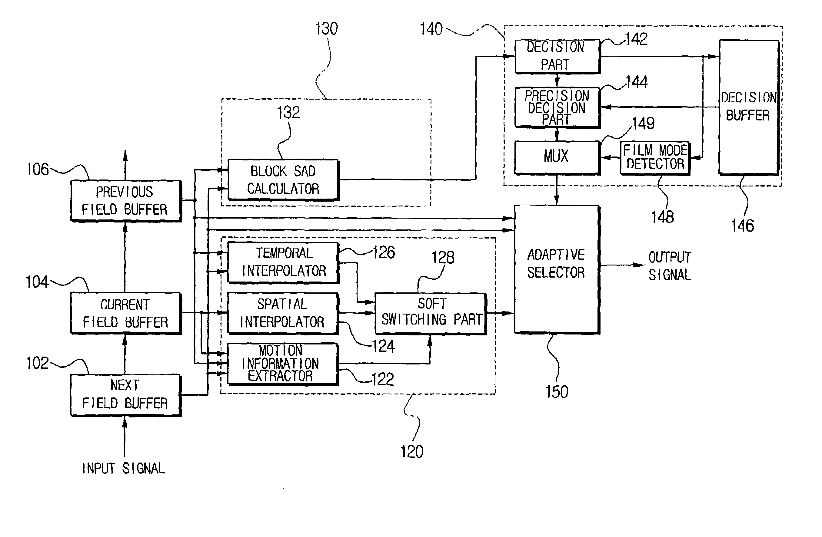
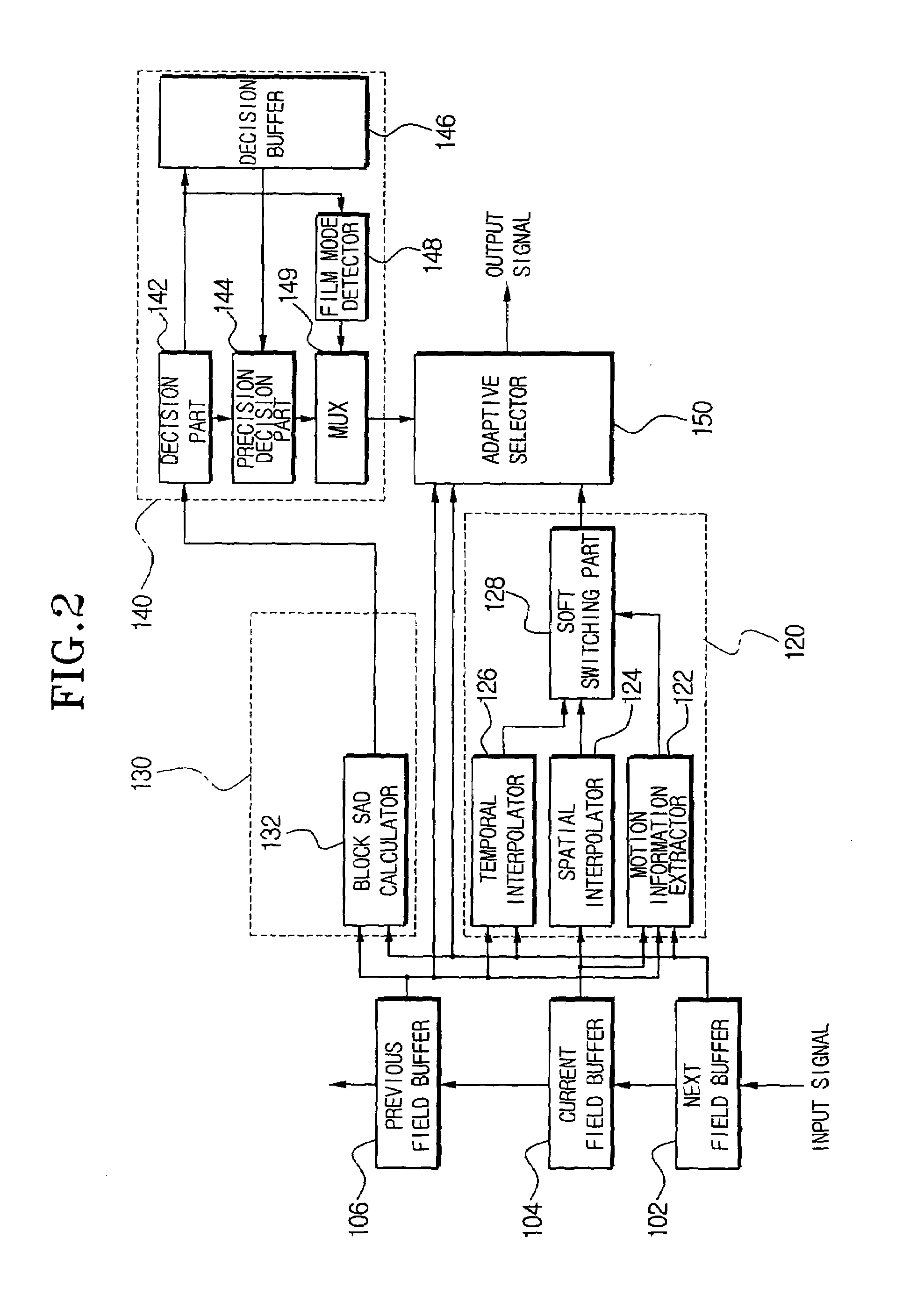
[0044]FIG. 2 is a block diagram for a deinterlacing apparatus according to an embodiment of the present invention. The present deinterlacing apparatus has a next field buffer 102, a current field buffer 104, a previous field buffer 106, a 3D interpolator 120, a zero motion estimator 130, a still region / film mode detector 140, and an adaptive selector 150.

[0045]The 3D interpolator 120 is constructed with a motion information extractor 122, a spatial interpolator 124, a temporal interpolator 126, and a soft switching part 128. A stil...


PUM


Abstract

A deinterlacing apparatus and method use a buffer unit having a previous field buffer, a current field buffer, and a next field buffer to store, sequentially, individual fields of an image signal; calculate a Sum of Absolute Difference (SAD) value of a predetermined search region unit with reference to a next field stored in the next field buffer and a previous field stored in the previous field buffer; determine whether the predetermined search region is a still region and whether a source of the image signal is a film based on the SAD value; uses a 3D interpolation unit to output adaptively a temporal interpolation value and a spatial interpolation value based on motion information; and adaptively select a deinterlacing result based on the previous field, the next field, and an output of the 3D interpolation unit according to a signal outputted from the still region/film mode detection unit.

Description

CROSS-REFERENCE TO RELATED APPLICATIONS[0001]This application claims the benefit of Korean Application No. 2002-43886, filed Jul. 25, 2002, in the Korean Intellectual Property Office, the disclosure of which is incorporated herein by reference.BACKGROUND OF THE INVENTION[0002]1. Field of the Invention[0003]The present invention relates to a deinterlacing apparatus and method, and, more particularly, to deinterlacing apparatus and method to distinguish and adaptively interpolate, accordingly, still regions and moving regions in an image.[0004]2. Description of the Related Art[0005]The interlaced scan mode and the progressive scan mode are typical scan modes in an image display device. The interlaced scan mode has been employed in general TVs, and, as shown in FIG. 1A to FIG. 1C, is the mode that divides one image frame into two fields and interlaces the two fields sequentially and alternately on the screen when displaying one image. The two fields are called a top and a bottom field,...

Claims


Application Information

Patent Timeline
IPC IPC(8): H04N7/01
CPCH04N9/45H04N7/012H04N7/0115H04N7/01
Inventor JUNG, YOU-YOUNGLEE, YOUNG-HOYANG, SEUNG-JOON
Owner SAMSUNG ELECTRONICS CO LTD
Why Eureka
Try Eureka