Problem area location in an image signal

Inactive Publication Date: 2006-06-06
DYNAMIC DATA TECH LLC
View PDF20 Cites 15 Cited by
  • Summary
  • Abstract
  • Description
  • Claims
  • Application Information

AI Technical Summary

Benefits of technology

[0012]It is, inter alia, an object of the invention to provide a straightforward and reliable occlusion detection and halo reduction. To this end, a first aspect of the invention provides a method and device for locating problem areas in an image si

Problems solved by technology

Every motion compensated scan-rate conversion method is confronted with the problem of occlusions in a sequence.
But in the regions where covering or uncovering occurs, and where the motion estimation is performed by analyzing two successive

Method used


Image

  • Problem area location in an image signal
  • Problem area location in an image signal
  • Problem area location in an image signal

Examples


Example

[0021]Our method aims first at localizing, in a robust and cost-effective way, the areas where vector-based algorithms for scan rate conversion can produce very strong and annoying artifacts. For those areas, several solutions are proposed, depending on the target quality of the up-conversion and on the cost constraints. The usefulness of this approach shall be proven in a comparison with the aforementioned alternatives, although their benchmarking has not yet been completed.

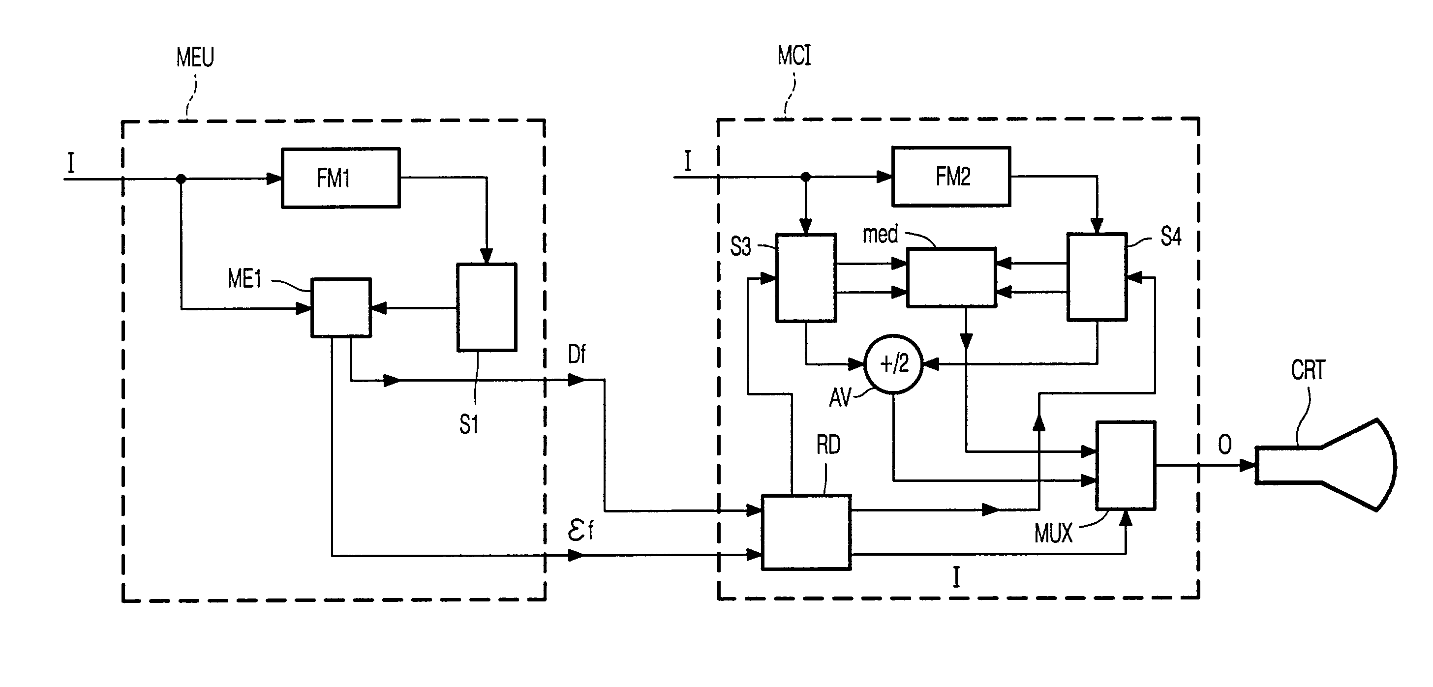
[0022]In order to detect areas in which covering or uncovering occur, the current algorithm just needs the information that is available in a motion vector field related to that frame, and a very limited processing of that information. In fact, the motion vector field already describes the temporal behavior of the sequence, generally obtained using more than one frame, thus no additional information is needed for only covering / uncovering detection.

[0023]The current algorithm does not need an ad hoc motion estima...


PUM


Abstract

In a method of locating problem areas in an image signal (I), a motion vector field (Df) is estimated for the image signal (I), and edges are detected in the motion vector field (Df). In a corresponding method of interpolating images between existing images (I), image parts are interpolated (MCI) in dependence upon a presence of edges; preferably, an order statistical filtering (med) is used at edges.

Description

CROSS-REFERENCE TO RELATED APPLICATIONS[0001]This is a continuation of U.S. patent application Ser. No. 09 / 374,696, filed Aug. 16, 1999 now U.S. Pat. No. 6,487,313.BACKGROUND OF THE INVENTION[0002]1. Field of the Invention[0003]The invention relates to problem area location in an image signal, and more specifically, to occlusion detection and halo reduction in motion compensated pictures.[0004]2. Description of the Related Art[0005]Every motion compensated scan-rate conversion method is confronted with the problem of occlusions in a sequence. Several approaches have been attempted to cope with it. In many cases, the effort has been devoted at improving the quality of the motion estimation method in order to have very precise motion boundaries (e.g., see Ref. 1). But in the regions where covering or uncovering occurs, and where the motion estimation is performed by analyzing two successive frames, motion estimation is an ill-posed problem (see Ref. 2) and cannot yield good results. T...

Claims


Application Information

Patent Timeline
IPC IPC(8): G06K9/48G06K9/36G06K9/40H04N5/14G06T7/20H04N7/01H04N19/895
CPCG06T7/2013H04N5/145H04N19/895H04N19/527H04N19/86H04N7/014G06T2207/10016G06T7/223
Inventor DE HAAN, GERARDPELAGOTTI, ANNA
Owner DYNAMIC DATA TECH LLC
Why Eureka
Try Eureka