Method and system for an on-chip AC self-test controller

a self-test controller and controller technology, applied in the direction of electronic circuit testing, measurement devices, instruments, etc., can solve the problem of becoming correspondingly more difficult to test and diagnose such circuits

Inactive Publication Date: 2006-06-06
GLOBALFOUNDRIES INC
View PDF8 Cites 38 Cited by
  • Summary
  • Abstract
  • Description
  • Claims
  • Application Information

AI Technical Summary

Problems solved by technology

As the design of integrated circuits has progressed, more and more circuitry is being disposed in increasingly dense patterns and it has become correspondingly more difficult to test and diagnose such circuits.

Method used


Image

  • Method and system for an on-chip AC self-test controller
  • Method and system for an on-chip AC self-test controller
  • Method and system for an on-chip AC self-test controller

Examples


Embodiment Construction

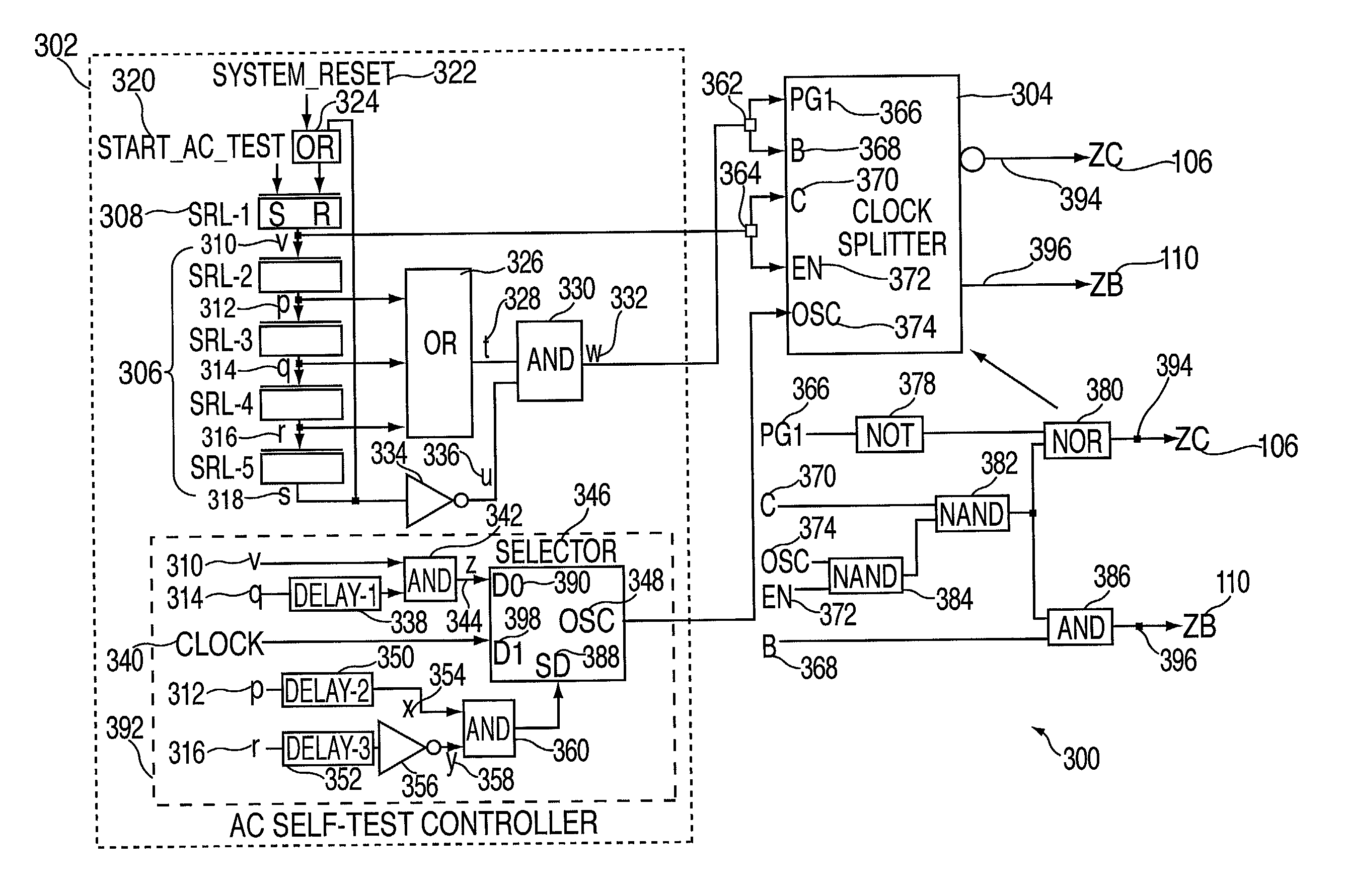
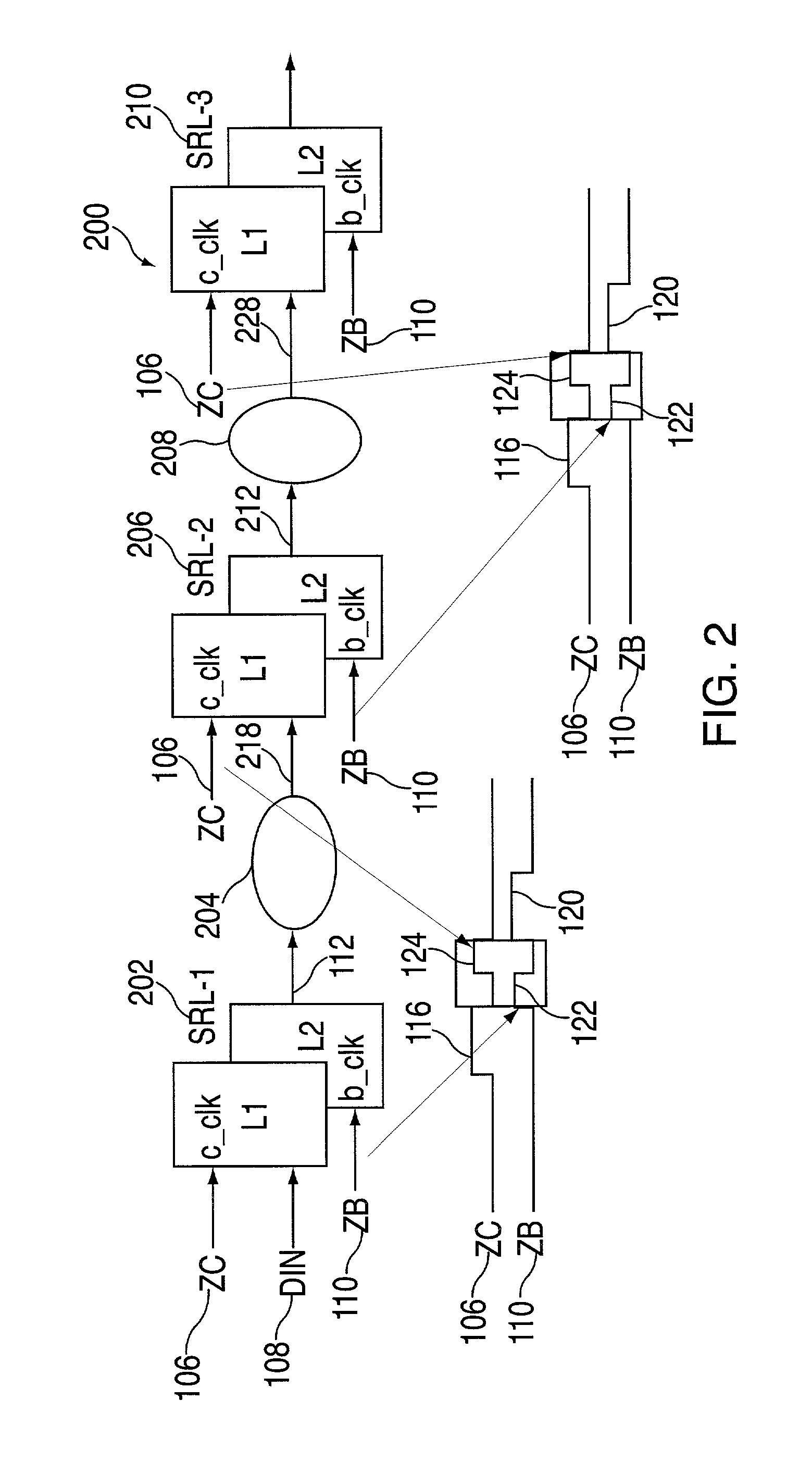
[0012]The present invention discloses a method to perform an AC self-test using a scheme that renders distribution and tuning of control signals to the clock splitters noncritical. In an exemplary embodiment, the AC self-test is performed by first initializing all the shift register latches (SRLs) with test data using a process that is known in the art. The initializing can be performed by scanning all the SRLs within the integrated circuit with a set of pseudo random data by pulsing the scan clocks as many times as needed to fill the SRLs with data. The A clock is typically the scan clock the causes the test data at the L1 input port to enter the L1 latch and the B clock is typically the scan clock that causes the data from the L1 latch to enter the L2 latch and the input port of the next L1 latch in the chain. The A clock should pulse last so that L1 and L2 contain different data at the end of the scan or initialization operation.

[0013]Once the SRLs are initialized, the AC self-te...


PUM


Abstract

A method for performing AC self-test on an integrated circuit, including a system clock for use during normal operation. The method includes applying a long data capture pulse to a first test register in response to the system clock, and further applying at an speed data launch pulse to the first test register in response to the system clock. Inputting the data from the first register to a logic path in response to applying the at speed data launch pulse to the first test register. Applying at speed data capture pulse to a second test register in response to the system clock. Inputting the output from the logic path to the second test register in response to applying the at speed data capture pulse to the second register. Applying a long data launch pulse to the second test register in response to the system clock.

Description

GOVERNMENT RIGHTS[0001]This invention was made with Government support under subcontract B338307 under prime contract W-7405-ENG-48 awarded by the Department of Energy. The Government has certain rights in this invention.FIELD OF THE INVENTION[0002]The present invention relates generally to a method of performing an AC self-test on an integrated circuit, and more particularly to performing the AC self-test using the same system clock that is utilized during normal system operation.BACKGROUND OF THE INVENTION[0003]As the design of integrated circuits has progressed, more and more circuitry is being disposed in increasingly dense patterns and it has become correspondingly more difficult to test and diagnose such circuits. Several methodologies for performing integrated circuit testing use level sensitive scan design (LSSD) techniques to facilitate circuit testing and diagnosis. Integrated circuit devices of interest typically contain blocks of combinatorial logic paths whose inputs an...

Claims


Application Information

Patent Timeline
Patent Type & Authority Patents(United States)
IPC IPC(8): G01R31/28G01R31/317G01R31/319
CPCG01R31/2891G01R31/31922G01R31/31724
Inventor FLANAGAN, JOHN D.HERRING, JAY R.LO, TIN-CHEE
Owner GLOBALFOUNDRIES INC
Why Eureka
Try Eureka