Folding knife with blade lock

a technology of blade lock and folding knife, which is applied in the field of folding knives, can solve the problems of lock failure and inadvertent release of the lock

Inactive Publication Date: 2006-06-13
SOG SPECIALITY KNIVES & TOOLS
View PDF26 Cites 59 Cited by
  • Summary
  • Abstract
  • Description
  • Claims
  • Application Information

AI Technical Summary

Benefits of technology

[0005]The present invention provides an improved lock for a folding knife having a blade pivotally attached to one end of a handle. The blade is movable between an open position in which the blade extends away from the handle and a closed position in which the blade is received within a groove of the handle. The tang portion of the blade, at the opposite side of the blade pivot from the sharpened blade portion, has a peripheral cam edge with a notch for receiving a lock finger or dog when the blade is in the open position. The outer periphery of the tang can have another notch positioned to receive the finger or dog when the blade is in the closed position. The lock finger or dog can be formed by the end of a link that pivots inside the handle in the same plane as the blade. The link is positioned to the rear of the tang of the blade and pivots between a forward swung detent or locking position and a rearward swung free or released position. In the detent or locking position, the dog end of the link rides on the peripheral cam edge of the tang for reception in one of the notches when the blade is in the corresponding position relative to the handle. The dog end of the link is biased forward toward the forward end of the handle and the outer periphery of the tang, and may be moved rearward manually to a released position by manipulation of one or more pins or buttons extending transversely of the locking link adjacent to its dog end. The button or buttons can project from a slot or slots in the handle.

Problems solved by technology

Despite the popularity of these structures, there still are instances of lock failure or, more often, inadvertent releasing of the lock.
Another problem is a lock which requires or encourages the user to have a finger or part of his or her hand in the path of a closing blade when the release mechanism is actuated, because of the arrangement of the parts and the actions necessary for releasing the lock.

Method used


Image

  • Folding knife with blade lock
  • Folding knife with blade lock
  • Folding knife with blade lock

Examples


Embodiment Construction

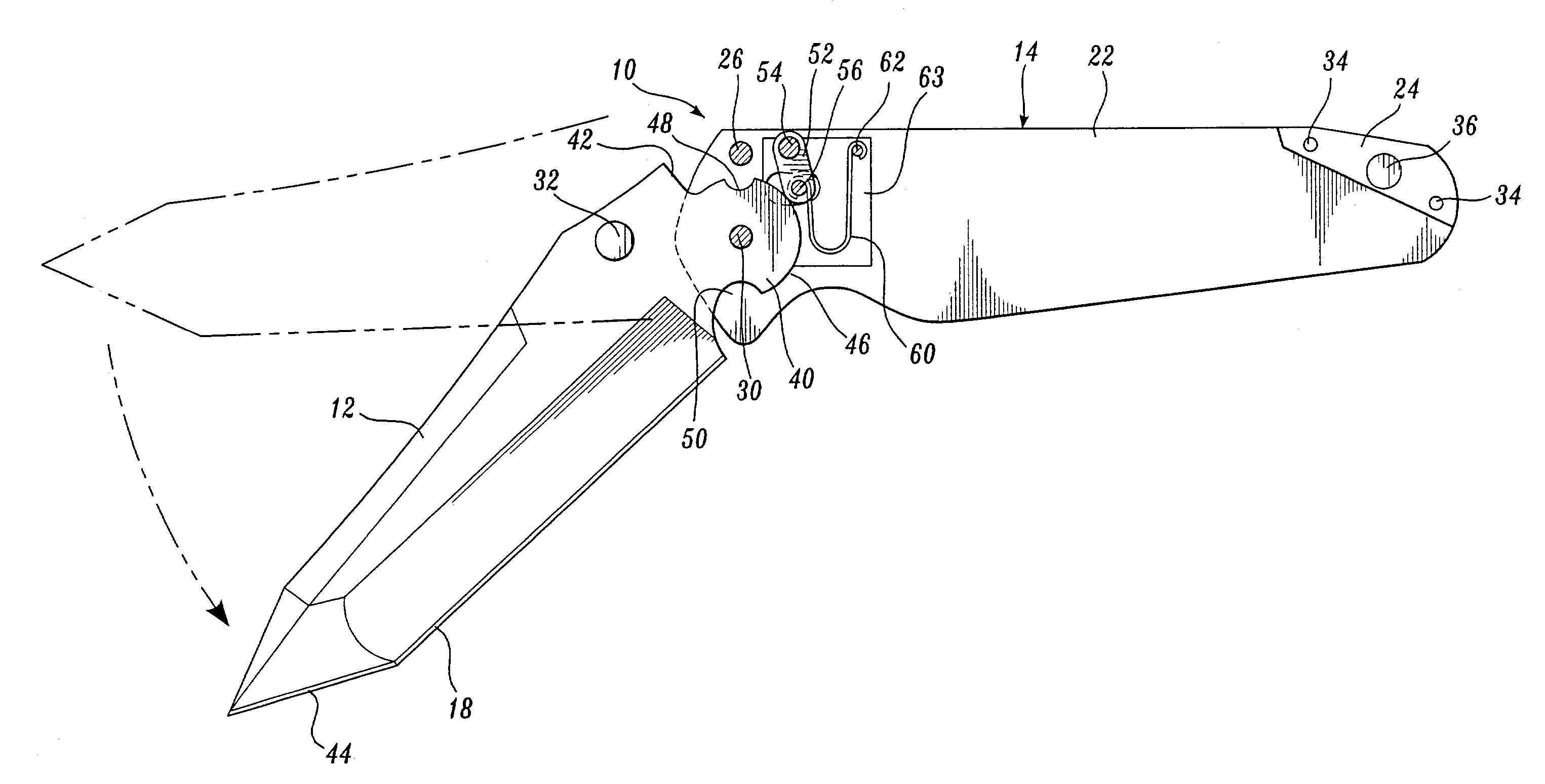
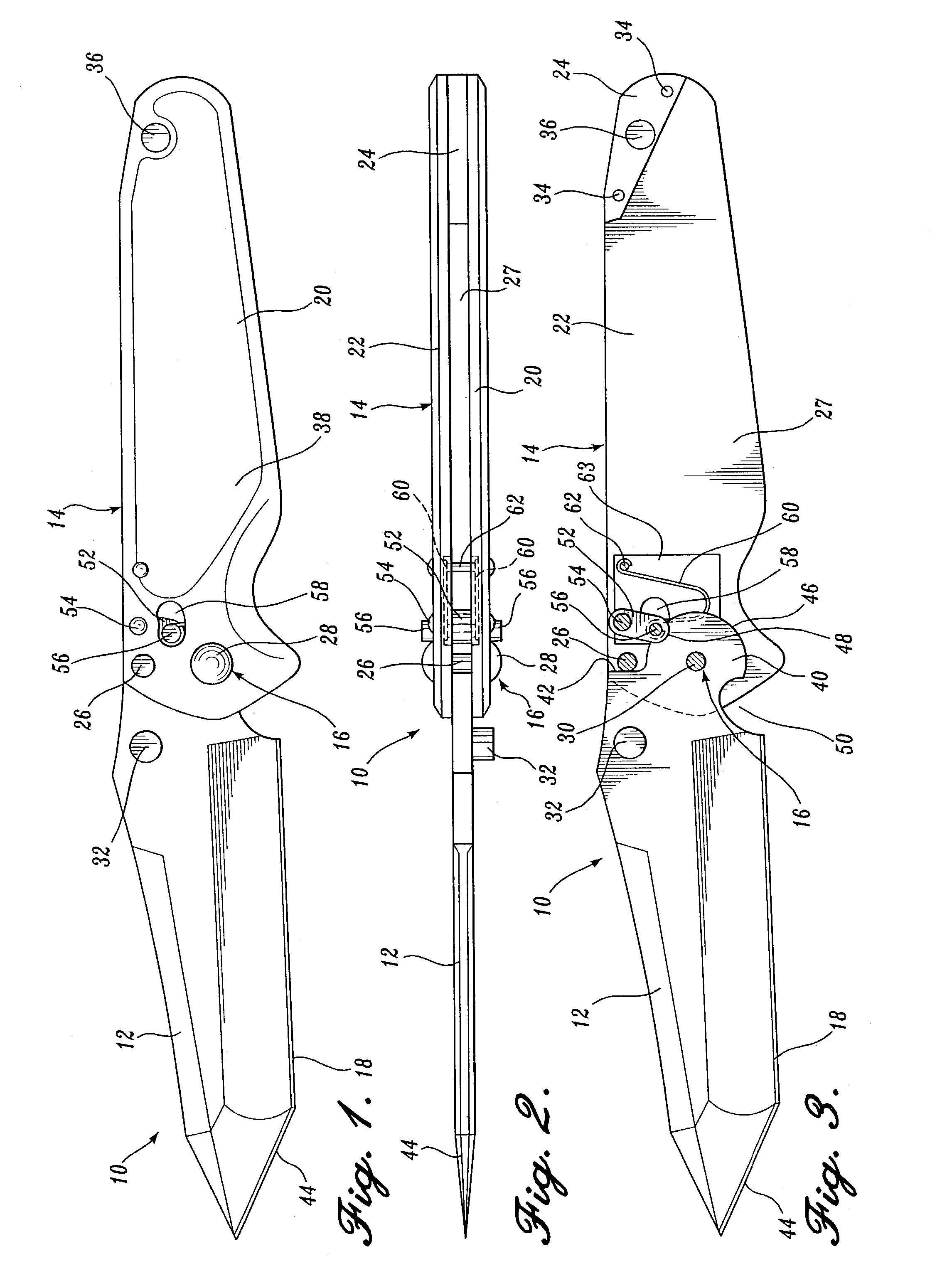
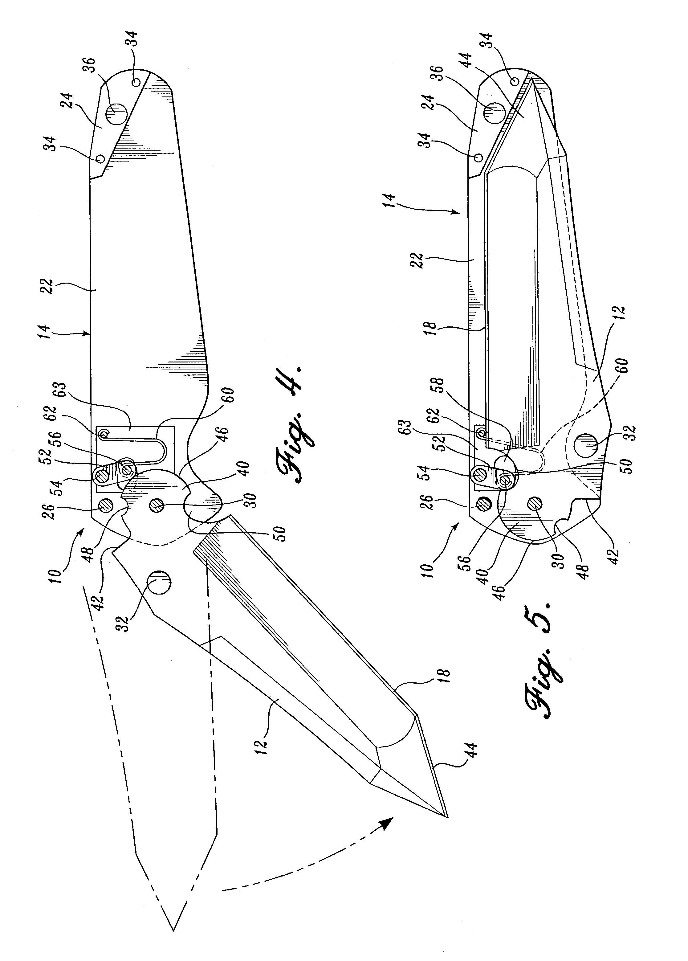
[0011]With reference to FIGS. 1–3, a folding knife 10 of the type with which the present invention is concerned has an elongated blade 12 attached to one end portion of a horizontally elongated handle 14 by a pivot pin 16. As described in more detail below, the blade 12 is swingable relative to the handle between the open or working position shown in FIGS. 1–3, in which the blade extends from the handle with its sharpened edge 18 exposed for use, and a closed position in which the blade, or at least its sharpened edge portion, is received in the handle. The present invention provides an improved mechanism by which the blade may be locked in the open position to prevent unintentional or unexpected closing of the knife which could bring the sharpened edge 18 into contact with the hand of a user and cause injury. Preferably, such a lock mechanism will be sturdy, reliable and conveniently operable, i.e., released without bringing the fingers or hand of the user into a dangerous position...


PUM


Abstract

The blade of a folding knife has a tang portion by which the blade is pivoted to a handle for swinging between an open position and a closed position. In the open position the blade extends from the handle with its sharpened edge exposed for use, whereas in the closed position the sharpened edge is received in a groove of the handle. A locking link is pivotally mounted on the handle for swinging in the same plane as the blade, with a swinging end of the locking link cooperating with a notch in the tang to automatically lock the blade in the open position. The blade can be released for movement to the closed position by manipulation of buttons exposed at the exterior of the handle, which buttons extend transversely from the swinging end portion of the locking link.

Description

CROSS-REFERENCE TO RELATED APPLICATION[0001]This application is a continuation of application Ser. No. 09 / 707,734, filed on Nov. 7, 2000 now abandoned.FIELD OF THE INVENTION[0002]This invention relates to folding knives and, more particularly, to a folding knife that is capable of being locked in an open position with the blade extending from a handle.BACKGROUND OF THE INVENTION[0003]A popular feature of folding knives is a locking mechanism that prevents the blade of the knife from closing unintentionally and unexpectedly. Two popular types of such locks include the lock back and the liner lock. The lock back structure provides a spring-biased lever mounted along one side of a handle. The lever has a front hook or tooth that engages in a notch in the tang portion of the blade, adjacent to the point of pivotal attachment of the blade to the handle. The liner lock structure provides a thin liner of sheet metal that springs into place behind a flat portion of the tang of the blade, th...

Claims


Application Information

Patent Timeline
Patent Type & Authority Patents(United States)
IPC IPC(8): B26B1/04
CPCB26B1/048
Inventor SAKAI, KIMI
Owner SOG SPECIALITY KNIVES & TOOLS
Why Eureka
Try Eureka