Vertical lift flying craft

a vertical lift and flying craft technology, applied in vertical landing/take-off aircraft, aircraft navigation control, transportation and packaging, etc., can solve the problems of affecting the flight experience of the aircraft, requiring substantial clearance of the wing, and presenting safety hazards, so as to achieve the effect of inherent lateral stability and stability

Inactive Publication Date: 2006-06-13
BALDWIN G DOUGLAS
View PDF31 Cites 64 Cited by
  • Summary
  • Abstract
  • Description
  • Claims
  • Application Information

AI Technical Summary

Benefits of technology

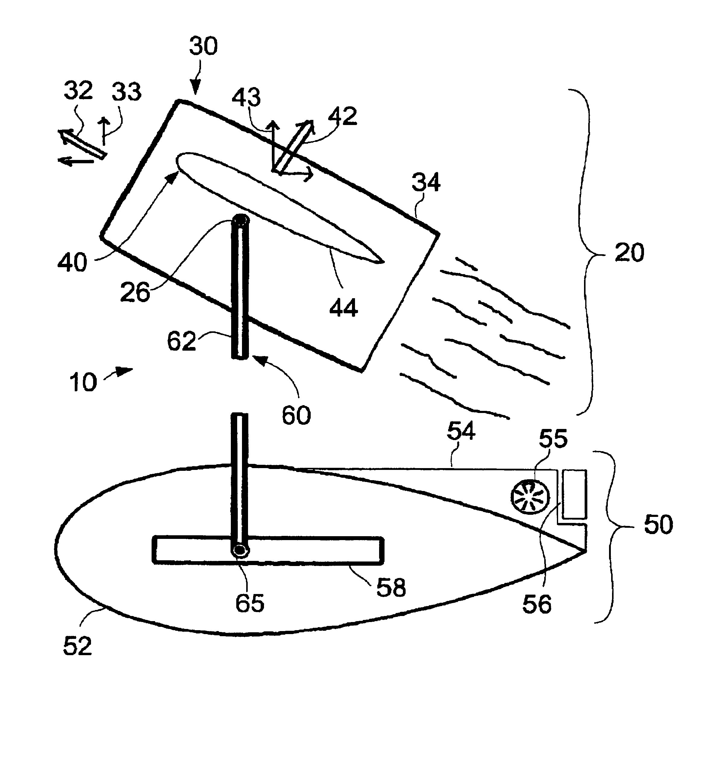
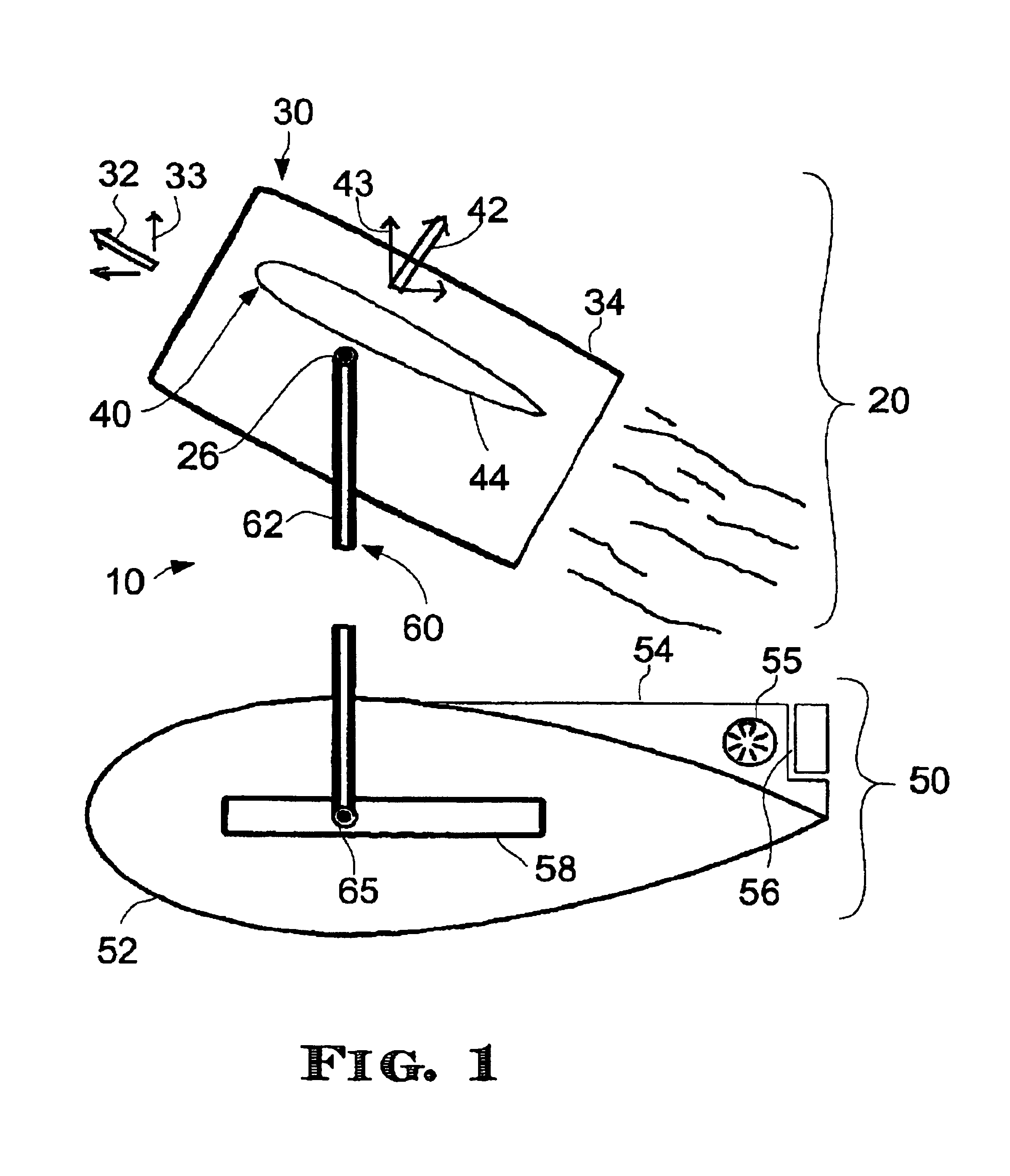
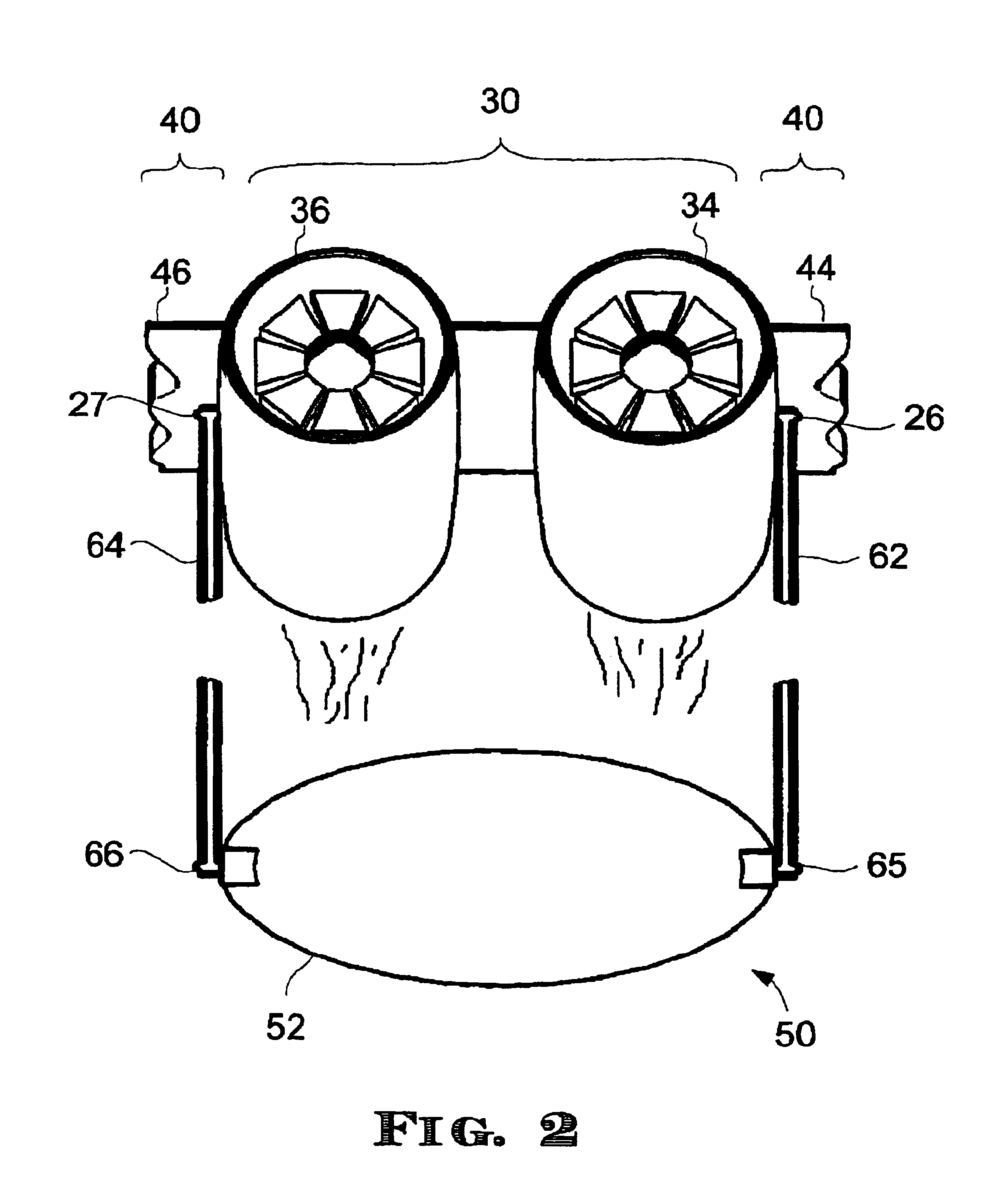
[0009]By suspending the payload unit from the lift unit through bearings, the suspension structure permits the payload unit to move about the rotational axis, independent of the direction of the force developed by the lift unit. By permitting the payload unit to move in such a manner, for example to reach an equilibrium position when acted upon by wind resistance during horizontal flight, the suspension structure suspends the payload unit while avoiding the development of a downward pitching moment.
[0012]According to another advantageous aspect of the present invention, the suspension structure is coupled to the payload unit, at one end, through a bearing. By permitting the payload unit to rotate independent of the orientation of the suspension structure, such a coupling arrangement provides particular advantages. For example, when the end of the suspension structure is coupled to the payload unit (through the bearing) above the center of mass of the payload unit, the payload unit can be expected to maintain a constant orientation, regardless of the orientation of the suspension structure. Consequently, the payload unit may remain substantially horizontal even when pushed aft of the lift unit by wind resistance. Advantages of having the payload unit maintain horizontal orientation include reduced wind resistance and, in flying craft where the payload unit is dimensioned and configured to accommodate passengers, increased passenger comfort.

Problems solved by technology

Although rotating-wing vertical lift aircraft (helicopters) have long been available, a rotating wing requires substantial clearance and can present safety hazards.
In addition, rotating-wing aircraft generally have poor cruise performance compared to fixed-wing aircraft.
Vertical lift aircraft other than rotating-wing aircraft do not enjoy such lateral stability because they are supported by a relatively compact source of thrust.
Although multiple thrusters can be employed for additional lateral stability, such an arrangement adds complexity and presents similar size disadvantages to those of a rotating-wing vertical lift aircraft.
Conventional approaches are problematic, however, when it comes to accommodating a payload while the vehicle makes the transition.
Permitting the payload to rotate with a vertical lift aircraft from a horizontal to vertical orientation is generally undesirable.
These deficiencies have a compound effect when a pilot attempts to land vertically or visually track ground-based targets because of the combined disorientation and discomfort they cause.
This class of aircraft presents a serious control problem, in that the mechanical rotations tend to be destabilizing and must be carefully coordinated with aerodynamic controls to keep the vehicle airborne.
Furthermore, the mechanism needed to affect the rotation tends to be heavy, which adds weight and reduces aircraft performance.
In addition, the mechanism represents a single failure point with potentially destabilizing failure modes.
When considered together with the above problems, the typical complexity of the mechanism can present a serious safety hazard.

Method used


Image

  • Vertical lift flying craft
  • Vertical lift flying craft
  • Vertical lift flying craft

Examples


exemplary embodiment 100

[0106]A first exemplary embodiment 100 of the invention includes a lifting unit 104 that employs, depending on the mode of flight, a fixed wing aerodynamic lift system 103 and a propeller thrusting system 105, which may be better understood with reference to FIGS. 3-8. A lift unit according to various aspects of the invention includes any heavier-than-air structure suitable for developing a force including an upward component without exerting a corresponding force on any external supporting structure or relying on aerostatic buoyancy. A lift unit can develop such a force from a suitably configured thrusting system, an aerodynamic lift system, or both.

[0107]A thrusting system or propulsion subsystem included in a thrusting system, according to various aspects of the invention, includes any structure suitable for developing a force primarily by accelerating fluid in an opposite direction In a thrust-based lifting unit, the force includes an upward component. The accelerated fluid can ...

exemplary embodiment 200

[0123]In exemplary embodiment 200, lift system 204 employs both an aerodynamic lifting system 1300 that functions primarily when lift unit 204 is in horizontal flight, and a thrusting system 1600 that provides lift primarily during stationary or slow-moving ascension or hover flight. Exemplary thrusting system 1600 of FIG. 16 is comprised of a first torque-producing propulsion subsystem 252 and a second torque-producing propulsion subsystem 254, wherein subsystem 252 is positioned in front of and rotates counter to subsystem 254. The two propulsion subsystems 252 and 254 are, in a preferred variation, counter-rotating 0.46 cubic inch displacement 30% nitromethane-powered piston engines. A 12 inch by 6 inch normal or tractor propeller 256 is mounted onto propulsion subsystem 252, and a 12 inch by 6 inch pusher propeller 258 is mounted onto propulsion subsystem 254. Thrusting system 1600 further includes a pair of two-ounce fuel tanks 260, one for each propulsion subsystem, and a glow...

exemplary embodiment 300

[0143]Suspension structure 306 of exemplary embodiment 300 is formed from a single piece of semi-elastic material having sufficient flexibility that the pair of second bearing members 312 can be spread apart from one another and slipped over the pair of first bearing members 310. The material of suspension structure 306 has sufficient inherent damping to prevent harmonic oscillations in all modes of operation. The inherent material properties of suspension structure 306 provides a damped elastic mechanism to moderate movement of suspension structure 306 parallel to the rotational axis, as illustrated in FIG. 26. Thus the aircraft has improved yaw control in vertical flight.

[0144]A variation of embodiment 300 (FIG. 24) has a facetted annular wing with a canted tail to further reduce the radar signature.

[0145]Embodiment 300 provides transport of payload unit 308 using a gyrodynamically neutral system for converting fuel to thrust with a single engine having a balanced counter-rotating...


PUM


Abstract

A disclosed vertical lift flying craft includes a lift unit that, during operation, develops a force including an upward component. A payload unit suspends from the lift unit. The payload unit suspends from the lift unit in such a way as to impart lateral stability while remaining capable of horizontal flight, without incurring the adverse effects of a downward pitching moment. In addition to a lift unit and a payload unit, the vertical lift flying craft includes a pair of bearings and a suspension structure, which cooperate to suspend the payload unit from the lift unit. Other systems and methods are also disclosed.

Description

CROSS-REFERENCE TO RELATED APPLICATIONS[0001]This application claims the benefit of priority under 35 U.S.C. §119 (a) and (b) to french Application No. 0201506, filed Feb. 7, 2002, and European Pat. No. EP 1,338,324 filed Jan. 20, 2003, the entire contents of which are both incorporated herein by reference. Both of those applications are incorporated herein by reference.BACKGROUND OF THE INVENTION[0002]Vertical Takeoff and Landing (vertical lift) aircraft have long been considered desirable because of their ability to hover in flight and transition in and out of flight without a runway, in addition to flying in a horizontal direction. Although rotating-wing vertical lift aircraft (helicopters) have long been available, a rotating wing requires substantial clearance and can present safety hazards. In addition, rotating-wing aircraft generally have poor cruise performance compared to fixed-wing aircraft. Consequently, other types of aircraft, for example lifting off in a “tail sitting...

Claims


Application Information

Patent Timeline
Patent Type & Authority Patents(United States)
IPC IPC(8): B64C17/04B64C11/00B64C27/28B64C29/00B64C31/036
CPCB64C11/001B64C17/04B64C31/036B64C29/0033B64C27/28
Inventor BALDWIN, G. DOUGLAS
Owner BALDWIN G DOUGLAS
Why Eureka
Try Eureka