Electrical connecting and fastening apparatus

a technology of electrical connections and fastening devices, applied in the direction of coupling device connections, cables, insulated conductors, etc., can solve the problems of time-consuming and cost-intensive wiring of electrical devices, high cost, and high labor intensity of electrical devices, and achieve simple and reliable contacting techniques, good flexibility of connecting devices, and increased flexibility of lines

Inactive Publication Date: 2006-06-13
WEIDMULLER INTERFACE GMBH & CO KG
View PDF18 Cites 4 Cited by
  • Summary
  • Abstract
  • Description
  • Claims
  • Application Information

AI Technical Summary

Benefits of technology

[0011]According to an important advantage of the present invention, one-half of the hitherto necessary plug and socket members can be eliminated, because it is now possible directly to contact the free ends of the coded connecting lines or cables only with one socket part. In particular, it is possible entirely to dispense with M5, M8 or M12 plug and socket parts. Electrical equipment will now be provided with a novel kind of socket for this purpose. Connecting cables can be processed in several ready-to-use lengths, and preferably even “off the drum” applications; in this case, the cables need only to be cut to length and stripped. For this purpose, in particular, the structure of automation technology systems, and especially the connectors of distributors with each other as well as the linkup of appliances such as actuators, sensors and the like to the distributors, will definitely be accelerated and simplified.
[0012]Preferably, the code profiling of the profile core member extends radially inwardly in the manner of a rib, and the code profiling of the guide projection extends in the manner of a guide groove contained in the outer circumference of the guide projection. In a practical manner, the profile core member furthermore is provided along its outer circumference with several spaced-apart grooves, which extend in the axial direction in the form of a helical spiral or screw on the outer surface of the profile core member, into which grooves are introduced in each case one of the conductors. In particular, in the case of this design, it is very easily possible to forget about the attachment of plug parts upon the connecting line and to contact said line directly with a socket part. Good flexibility of the connecting device can be implemented by means of the spiral-like arrangement of the conductors and the coding devices. The spiral-like profiling furthermore directs the conductors particularly well to the contacts, in particular, toward the resilient cutting contacts. If the outer profiling is not uniformly distributed along the circumference, then a coding function can be performed with it if, during the insertion into the socket whereby it engages a corresponding inside coding means on the socket.
[0013]The socket member can either be attached to or formed on an electrical appliance such as a distributor, or with an additional free end of a connecting line, or on a coupling with two socket parts, for example, to extend a connecting line. Preferably, however, a connection is established directly between two socket parts, for example, adjoining electrical appliances directly with a connecting line with its two free ends.
[0014]Furthermore, the conductors are formed with a rectangular cross-section in the fashion of a band and / or they consist of a plurality of metal core leads and / or a preferably expansible and / or flattenable metal braiding in order to increase the flexibility of the line.
[0015]The contacts are made as insulation cutting contacts, in particular, resilient insulation piercing contacts, whereby the guide projection is used as a thrust bearing for supporting the conductors during the piercing of the insulation. In this way, one can come up with a simple and particularly reliable contacting technique. As an alternative, it is also conceivable that the contacts would be made as resilient contacts for engagement with bare conductors.

Problems solved by technology

As has become known in the prior art, the wiring of electrical devices is often relatively laborious and therefore time-consuming and cost-intensive.
For example, in the field of automation technology for buildings and the like, electrical devices are often connected with each other by means of a high type of protection (IP 65) and more, often with plug connectors by way of the so-called M5, M8 or M12 standard that have proved to be technically effective but often to be relatively expensive.

Method used


Image

  • Electrical connecting and fastening apparatus
  • Electrical connecting and fastening apparatus

Examples


Embodiment Construction

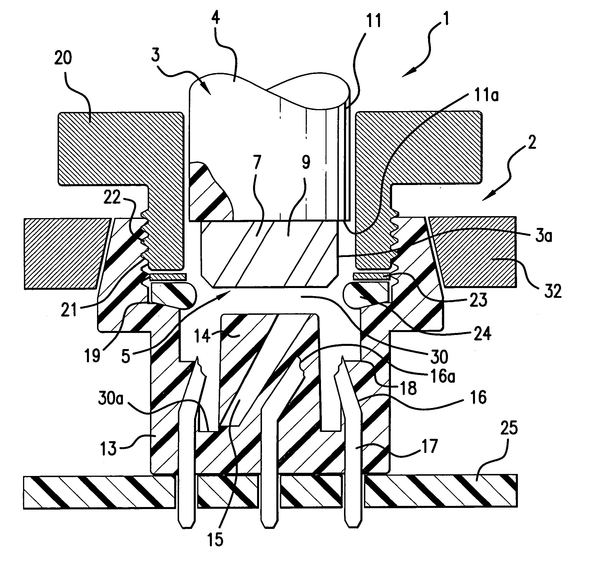
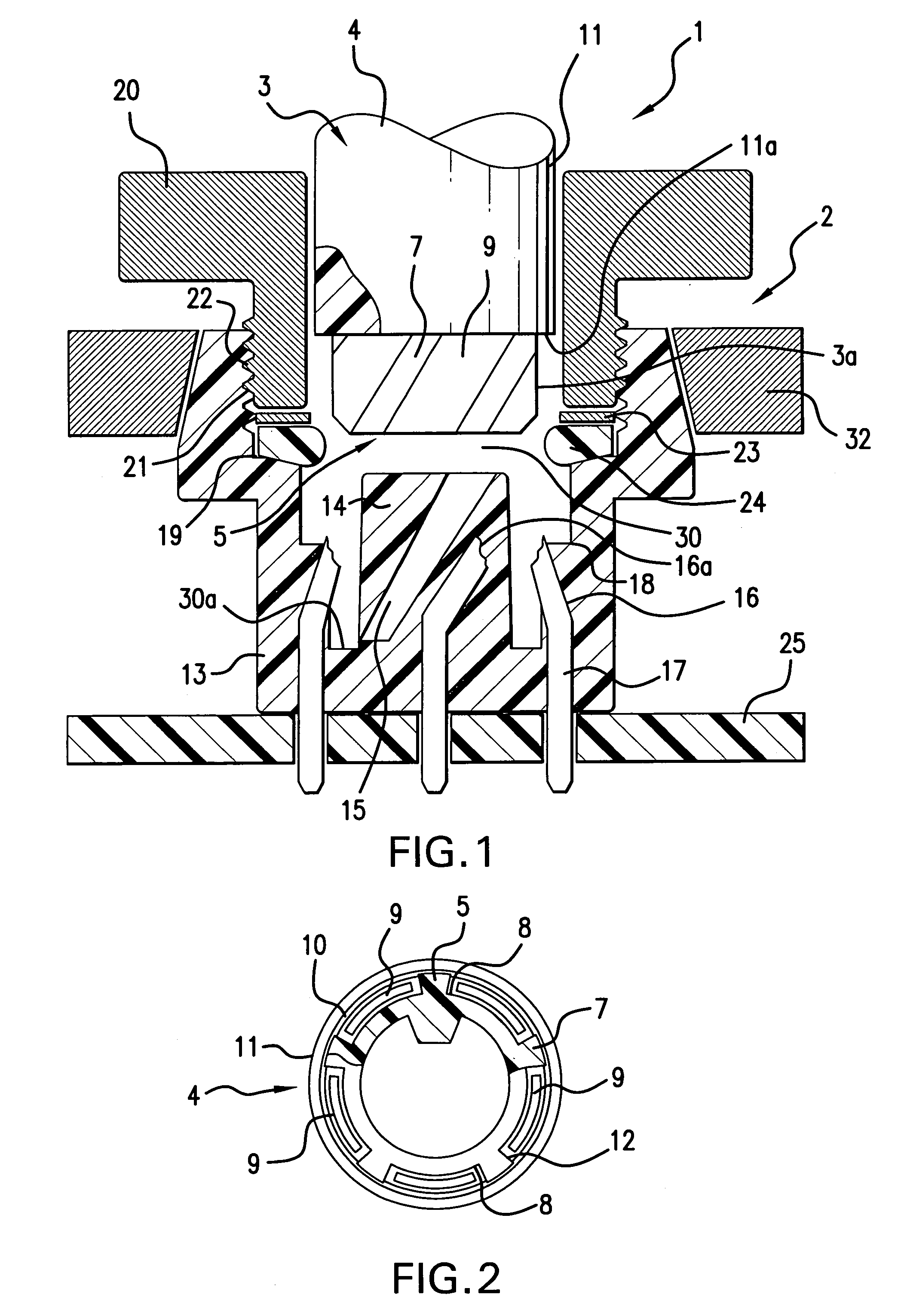
[0019]Referring first more particularly to FIG. 1, the connecting and fastening apparatus 1 of the present invention includes a cylindrical vertically arranged socket member 2 the upper end of which contains a bore 30 having a bottom wall 30a. Extending downwardly into the bore 30 is the leading one end 3 of a hollow electrical cable 4 that includes a tubular core member 5 formed of a suitable insulating synthetic plastic material. On its inner circumferential surface, the core member 5 is provided with a helical guide rib 6 having a tapered cross-sectional configuration that converges radially inwardly, as best shown in FIG. 2. On its outer circumferential surface, the core member 5 is provide with helical ribs arranged between helical grooves 8 that receive helical electrical conductors 9, respectively. Shown in FIG. 2, the conductors 9 have a flat cross-sectional configuration. The conductors are either in the form of flat bands, or as a braid formed from a plurality of small con...


PUM

PropertyMeasurementUnit
diameteraaaaaaaaaa
outer diameteraaaaaaaaaa
electricalaaaaaaaaaa

Abstract

An electrical connecting and fastening apparatus includes a guide arrangement for respectively connecting a plurality of conductors of a hollow cable with a plurality of stationary contacts mounted in circumferentially spaced relation within a bore contained in one end of a cylindrical socket member, the guide arrangement being so operable that as the cable is progressively inserted into the socket member bore, the leading end of the cable is rotated and twisted about its longitudinal axis relative to the remaining portion of the cable and to the socket member, thereby to effect positive electrical engagement between the conductors and the stationary contacts, respectively. In a first embodiment, the conductors are insulated, and the contacts are of the insulation piercing type. In another embodiment, the conductors are bare, and the stationary contacts are resilient and are biased toward engagement with the conductors. A lock nut arrangement serves to lock the cable to the socket member.

Description

BACKGROUND OF THE INVENTION[0001]1. Field of the Invention[0002]An electrical connecting and fastening apparatus includes a guide arrangement for respectively connecting a plurality of conductors of a hollow cable with a plurality of stationary contacts mounted in circumferentially spaced relation within a bore contained in one end of a cylindrical socket member, the guide arrangement being so operable that as the cable is progressively inserted into the socket member bore, the leading end portion of the cable is rotated and twisted about its longitudinal axis relative to the remaining portion of the cable and to the socket member, thereby to effect positive electrical engagement between the respective conductors and the stationary contacts. In a first embodiment, the conductors are insulated, and the contacts include insulation piercing means. In another embodiment, the conductors are bare, and the stationary contacts are resilient and are biased toward engagement with the respecti...

Claims


Application Information

Patent Timeline
Patent Type & Authority Patents(United States)
IPC IPC(8): H01R13/58H01B7/40H01R9/03H01R13/645H01R13/646
CPCH01R9/031H01R12/515H01R24/50H01R13/5816H01R2103/00H01R13/6456
Inventor BURY, JOACHIM
Owner WEIDMULLER INTERFACE GMBH & CO KG
Why Eureka
Try Eureka