
Disk prosthesis for cervical vertebrae with controlled clearance

a technology of cervical vertebrae and prosthesis, which is applied in the field of cervical vertebrae disk prosthesis, can solve the problems of reducing the height of the intersomatic space, perturbing the functional articular unit, and anatomic and functional destruction of the vertebral disk and segmen

Active Publication Date: 2006-06-13
SCIENTX
View PDF10 Cites 100 Cited by
  • Summary
  • Abstract
  • Description
  • Claims
  • Application Information

AI Technical Summary

Problems solved by technology

It is known that an intervertebral disk may undergo changes such as compression, deformation, shift or wear and, more generally, degeneration associated with mechanical stress on it and leading to anatomic and functional destruction of the vertebral disk and segment.
This disk alteration modifies the mechanical behaviour of the disk and results in a reduction in the height of the intersomatic space, in turn perturbing the functional articular unit.
This results in instability, in particular inducing an arthrosis reaction, a source of pain and osteophytic processes.
However, such a disk prosthesis for lumbar vertebrae is not suitable to replace the disk of cervical vertebrae since such a prosthesis does not allow the cervical vertebrae to recover their natural mobility.
In addition, the shape of the articulation knob is relatively difficult to produce properly and is sensitive to break and crack phenomena, thereby reducing the life of the prosthesis.

Method used


Image

  • Disk prosthesis for cervical vertebrae with controlled clearance
  • Disk prosthesis for cervical vertebrae with controlled clearance
  • Disk prosthesis for cervical vertebrae with controlled clearance

Examples


Embodiment Construction

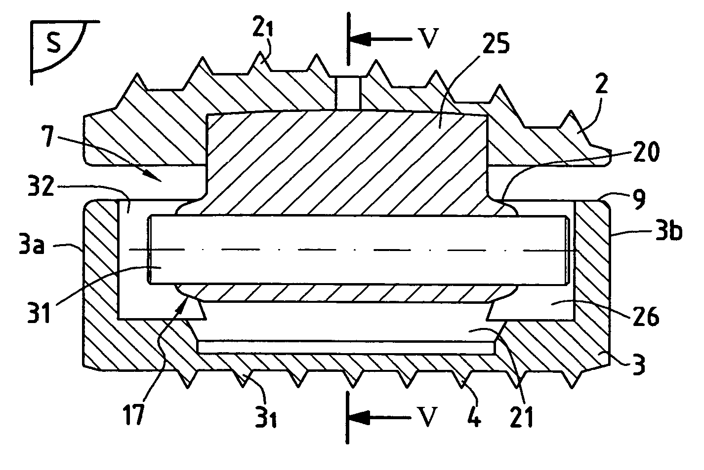
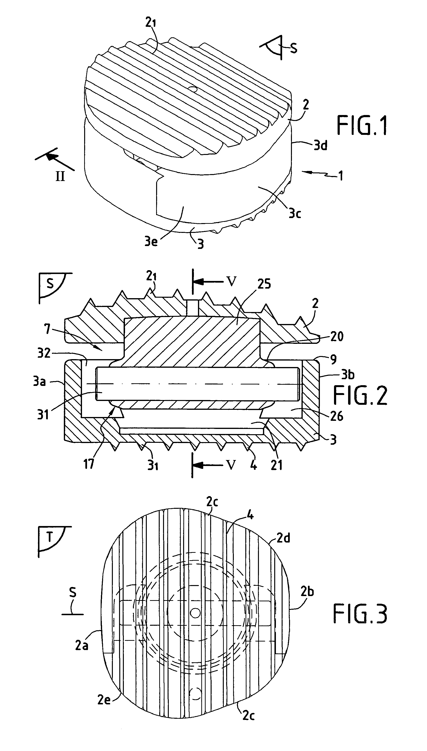
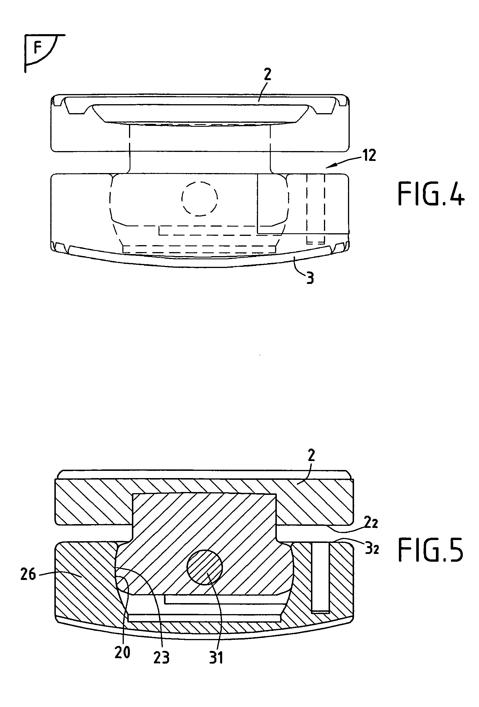
[0033]As more specifically indicated in the figures, the purpose of the invention concerns a disk prosthesis 1 to be implanted in the place of a disk between two adjacent cervical vertebrae. Cervical prosthesis 1 according to the invention comprises a first so-called upper plate 2 in the illustrated example and a second so-called lower plate 3. Plates 2 and 3 are intended to be fixed on neighbouring cervical vertebrae and each present an outer side, respectively 21, 31, of roughly similar dimensions adapted to take the exact shape of the associated articular surfaces.

[0034]In accordance with the invention, plates 2 and 3 present an anatomic profile that can be adapted to the intervertebral space. Therefore, as indicated more specifically in FIG. 2, the first plate 2 presents a convex profile in the sagittal plane S, while the second plate 3 presents a roughly flat profile in the same sagittal plane S. Moreover, as more specifically indicated in FIG. 4, the second plate 3 has a conve...


PUM


Abstract

A disk prosthesis includes first and second plates (2, 3) to be fixed on neighboring cervical vertebrae and an articulation arrangement (7) inserted between the two plates in a superposed position. The articulation arrangement allows for flexion-tension movements in a sagittal plane (S) according to a limited clearance, lateral inflexion movements in a plane perpendicular to the sagittal plane (S) according to limited angular clearance, and relative rotation movements between the first and second plates according to a limited angular clearance. The first and second plates are assembled to form a prosthesis of a single piece.

Description

FIELD OF THE INVENTION[0001]The purpose of the invention concerns a disk prosthesis for cervical vertebrae intended for substitution for the fibro-cartilaginous disk providing the connection between the cervical vertebrae of the spinal column.BACKGROUND ART[0002]It is known that an intervertebral disk may undergo changes such as compression, deformation, shift or wear and, more generally, degeneration associated with mechanical stress on it and leading to anatomic and functional destruction of the vertebral disk and segment. This disk alteration modifies the mechanical behaviour of the disk and results in a reduction in the height of the intersomatic space, in turn perturbing the functional articular unit. This results in instability, in particular inducing an arthrosis reaction, a source of pain and osteophytic processes. In the same way, nucleus pulposus herniation may arise, requiring the removal of the cervical disk.[0003]Therefore, a proposal was made to replace the defective d...

Claims


Application Information

Patent Timeline
IPC IPC(8): A61F2/44A61F2/00A61F2/30
CPCA61F2/4425A61F2002/30331A61F2002/30393A61F2002/30649A61F2310/00179A61F2220/0025A61F2220/0033A61F2310/00011A61F2002/30904
Inventor CARLI, OLIVIERBEN-MOKHTAR, MOURAD
Owner SCIENTX
Learn More