Energy storing foot prosthesis with improved plantar flexion

a technology of plantar flexion and foot prosthesis, which is applied in the field of foot prosthesis, can solve the problems of requiring significant time, effort and money, and prior art devices more nearly achieving the desired ease of adjustment, and achieve the effect of easy adjustmen

Inactive Publication Date: 2006-06-13
PHILLIPS VAN L
View PDF26 Cites 21 Cited by
  • Summary
  • Abstract
  • Description
  • Claims
  • Application Information

AI Technical Summary

Benefits of technology

[0010]It is, therefore, one object of my invention to provide a foot-prosthesis which can be easily adjusted without the necessity of removing the foot from the vertical pylon of an amputee's prosthetic leg. This will allow an active amputee to participate in a wide variety of activities without the necessity of frequent visits to the prosthetist.
[0011]In one embodiment, the present invention provides a foot prosthesis characterized by an easily removable auxiliary support member, herein also termed an auxiliary ankle or second foot portion, in conjunction with a primary support member, herein termed the forefoot member or first foot portion, and a lower support member, herein termed the sole member or third foot portion. The primary and lower support members are of such character as to be easily adaptable to provide size adjustment or accommodation of different spring rates to suit the size of foot, or of the stride and weight of the amputee. The auxiliary support member provides further adjustment to accommodate varying activity levels of a given amputee. The ease of removal of the auxiliary support member provides a degree of quick and easy adjustment previously unobtainable with prior prosthetics.
[0013]Another object of the invention is the incorporation in a prosthetic foot of the aforementioned character of compressible members in order to achieve a gradual dynamic transition, which can further improve the degree of adjustability of the prosthesis.
[0014]The particular location of attachment of the auxiliary support member allows for increased performance. Plantar flexion can be increased by not limiting the flexibility of the forefoot portion during heel strike, yet the ankle portion is still stiffened by the auxiliary support member during toe off. The inclusion of compressible members disposed between the auxiliary support member, and the forefoot member allows for further adjustability of performance characteristics.

Problems solved by technology

Although many prosthetic devices have attempted to simulate the ambulation of a normal foot, very few of them are readily adjustable in terms of their performance characteristics.
Certainly, some prior art devices more nearly achieve the desired ease of adjustability than do others.
Disassembly of the prosthetic foot from the pylon requires a significant amount of time, effort, and money as it must be done by a prosthetist.
Moreover, the dynamic performance of many of these other prior art devices is relatively stiff and immediate, and generally cannot produce adequate plantar flexion during heel strike, while retaining sufficient stiffness for toe-off.

Method used


Image

  • Energy storing foot prosthesis with improved plantar flexion
  • Energy storing foot prosthesis with improved plantar flexion
  • Energy storing foot prosthesis with improved plantar flexion

Examples


Embodiment Construction

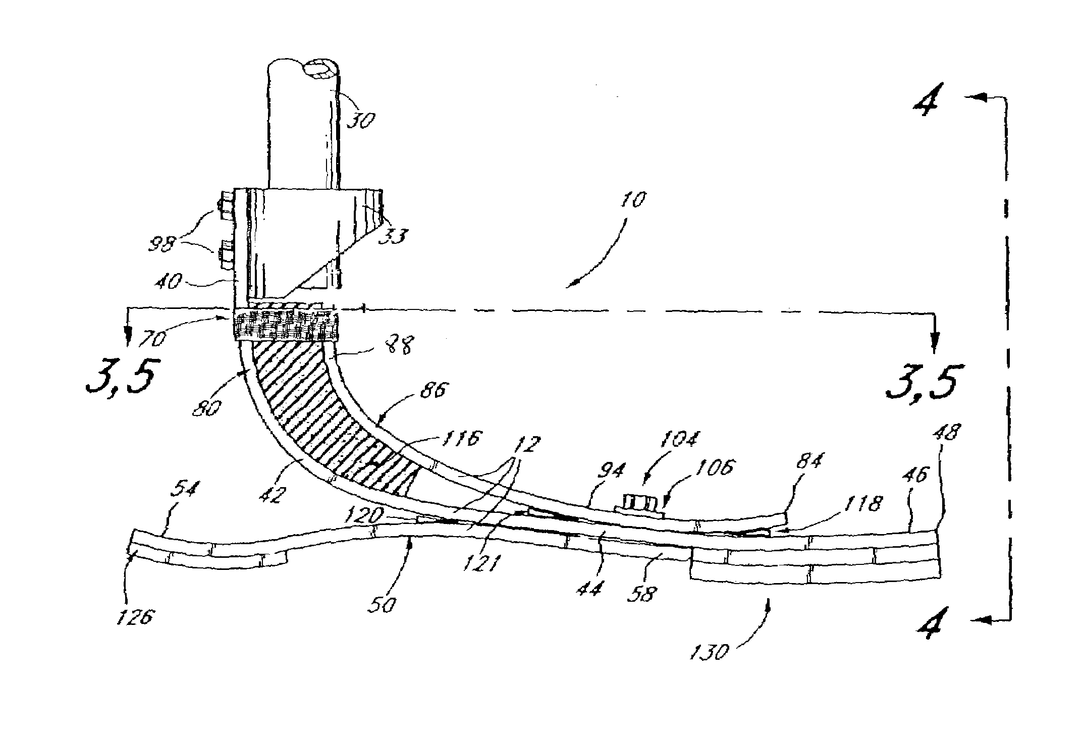
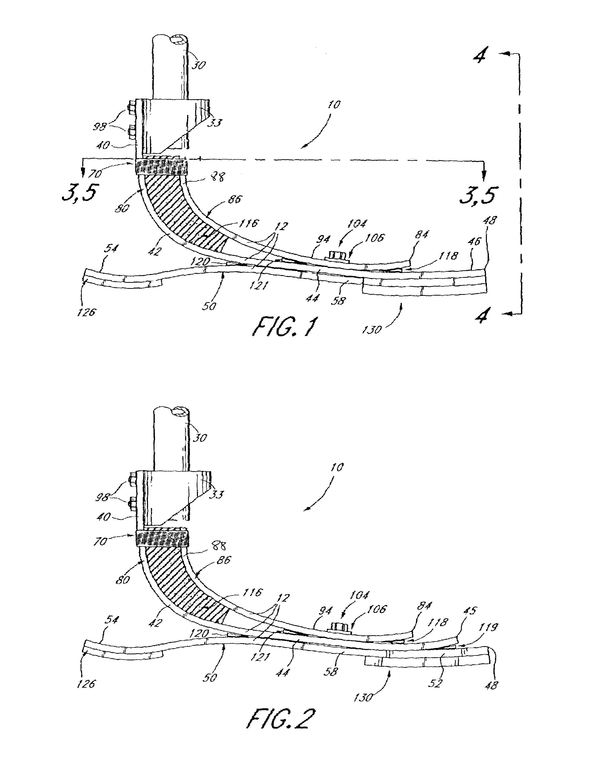
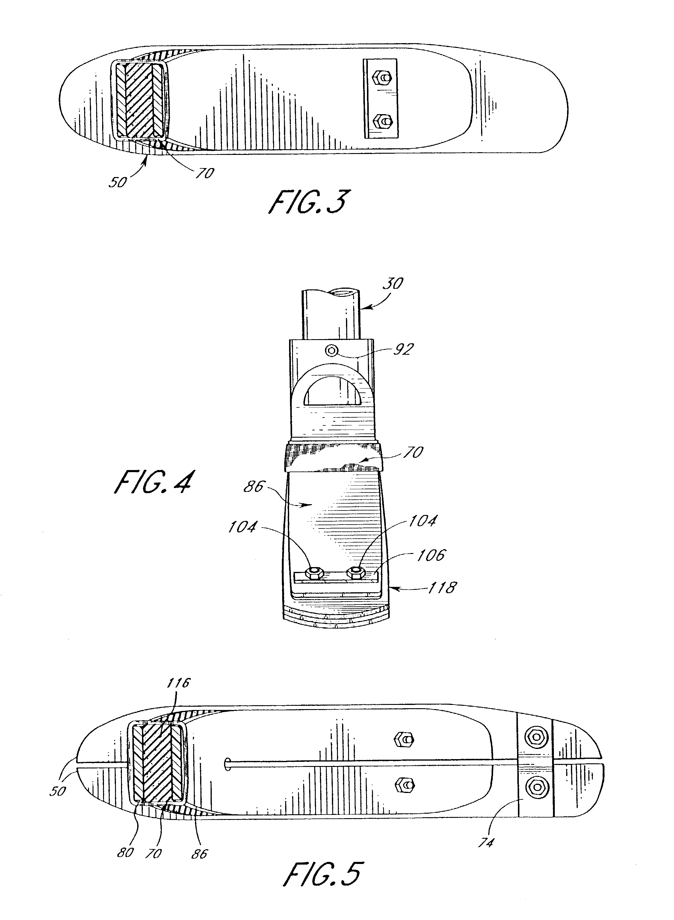
[0027]Referring to the drawings, and particularly to FIG. 1, I show one preferred embodiment of a foot prosthesis 10 constructed in accordance with the teachings of the invention. The foot 10 generally includes a forefoot member 80, a sole member 50, and an auxiliary support member 86 operatively and demountably attached to each other at the arch section 44. Attachment is preferably accomplished using suitable nut and bolt combinations 104 associated with a load-transmitting metallic plate 106. The auxiliary member is preferably attached to the forefoot member such that the auxiliary member may add to the stiffness of the ankle portion of the forefoot member. If desired, a retaining band 70 may be provided at the ankle section 42. A compressible member 116 may be provided between the auxiliary member, and the forefoot member. Function blocks 118, 120, 121, and 119 (FIG. 2) may also be provided in order to vary the length of the effective lever arms of the various members. If indicat...


PUM


Abstract

A prosthetic foot characterized by an easily exchangeable auxiliary ankle member demountably attached to forefoot and sole portions, which are in turn demountably and interchangeably connected. The forefoot, heel and auxiliary ankle portions are fabricated from polymer impregnated and encapsulated laminates, including such laminates as carbon fibers and / or fiberglass or synthetic fibers such as Kevlar. The easily demountable connection of the auxiliary ankle permits interchangeability thereof to match the activity schedule of the wearer utilizing the prosthetic foot without the necessity of frequent visits to the prosthetist. A compressible member between the forefoot member and the sole member, and function blocks located between the various members provide additional adjustability. The orientation of the auxiliary ankle member and compressible member also allows for increased plantar flexion.

Description

CROSS-REFERENCE TO RELATED APPLICATIONS[0001]This application is a continuation of U.S. application Ser. No. 09 / 945,092, filed Aug. 30, 2001 now abandoned, which claims the benefit of U.S. Provisional Application No. 60 / 229,113, filed Aug. 30, 2000, the entirety of each one of which is hereby incorporated by reference herein.BACKGROUND OF THE INVENTION[0002]1. Field of the Invention[0003]This invention relates to foot prostheses in general, and specifically to a prosthetic foot characterized by a unitary foot and heel construction, and an auxiliary ankle construction which permits the flexibility of the prosthesis to be selectively determined and easily changed.[0004]2. Background of the Invention[0005]Although many prosthetic devices have attempted to simulate the ambulation of a normal foot, very few of them are readily adjustable in terms of their performance characteristics. Adjustability is especially desirable among amputees who frequently participate in a variety of physical ...

Claims


Application Information

Patent Timeline
Patent Type & Authority Patents(United States)
IPC IPC(8): A61F2/66A61F2/50
CPCA61F2/66A61F2002/5007A61F2002/6678A61F2002/665A61F2002/5083
Inventor PHILLIPS, VAN L.
Owner PHILLIPS VAN L
Why Eureka
Try Eureka