Method and apparatus for MR image acquisition

a technology of mr image and apparatus, applied in the field of mr image acquisition, can solve the problem of long time-consuming 400 ms

Inactive Publication Date: 2006-06-13
GENERAL ELECTRIC CO
View PDF7 Cites 11 Cited by
  • Summary
  • Abstract
  • Description
  • Claims
  • Application Information

AI Technical Summary

Problems solved by technology

Firstly, for the heart, the duration of 400 ms is lengthy as the heart moves far too much during this period.

Method used


Image

  • Method and apparatus for MR image acquisition
  • Method and apparatus for MR image acquisition
  • Method and apparatus for MR image acquisition

Examples


Embodiment Construction

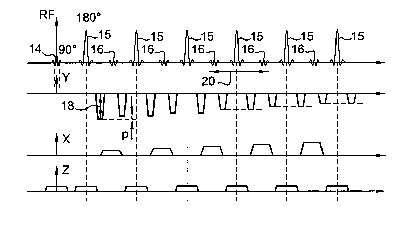
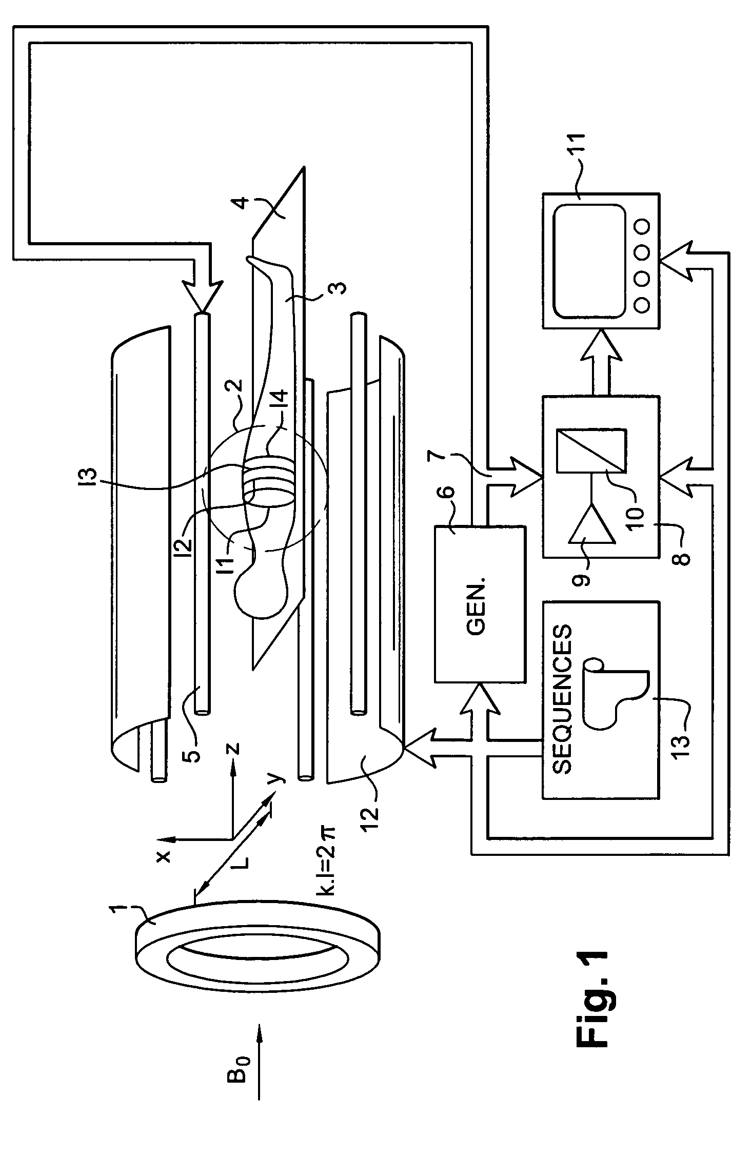
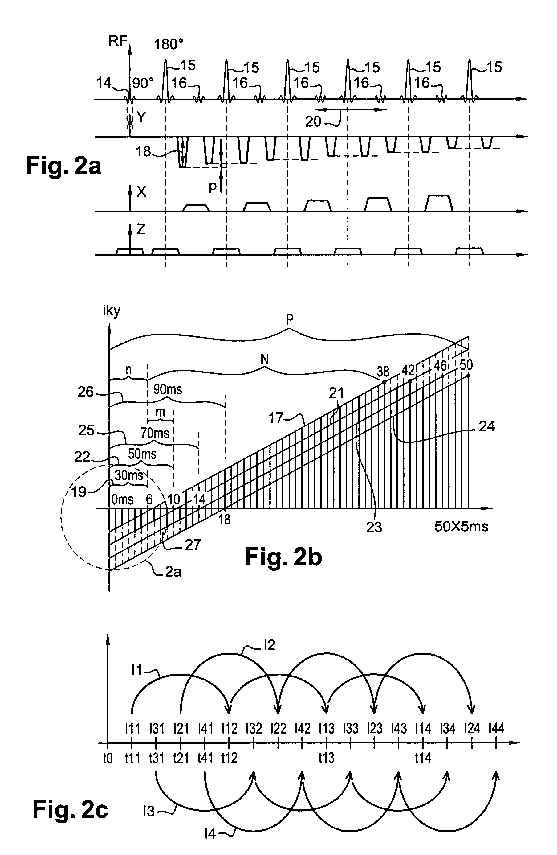
[0032]FIG. 1 shows an NMR apparatus that can be used to implement an embodiment of the method according to the invention. Generally speaking, this apparatus comprises means 1 for producing a constant, intense and uniform magnetic field B0 in a region of examination 2. An object 3, such as a body, is supported for example by a table 4 is brought close to the region 2. Throughout the procedure, the body 3 remains subjected to the magnetic field B0. The part 2 of the object 3 subjected to the examination is more particularly the region of the heart of the patient 3. Means for excitation and sensing, for example, an antenna 5 connected to a generator 6, is used to prompt the excitation of the magnetic moments of the particles of the body 3 located in the zone 2. In one example, the antenna 5 is a bar antenna capable of producing a rotating excitation field by a phase-shifted excitation of each of the bars.

[0033]The excitations are temporary. At the end of these excitations, the antenna ...


PUM


Abstract

An NMR image of a patient's heart uses SSFSE (single shot fast spin echo) type pulses to condition the body by a preparation of a phase-encoding gradient pulse whose duration differs from one sequence to another so as to define, from one sequence to another, a different effective echo time. At each sequence an image is displayed representing the discrimination of the contributions of the particles of the body as a function of their time T2 compared with this effective time. For the heart, with a single respiration on the part of the patient, lesions due to infarction and transplant rejection are revealed.

Description

CROSS-REFERENCE TO RELATED APPLICATIONS[0001]This application claims the benefit of a priority under 35 USC 119(a)–(d) to French Patent Application No. 04 51659 filed Jul. 26, 2004, the entire contents of which are hereby incorporated by reference.BACKGROUND OF THE INVENTION[0002]An embodiment of the present invention is a method and apparatus for the acquisition of an image by nuclear magnetic resonance (NMR). The acquired image is that of a part of an object, such as body, subjected to an intense magnetic field known as an orienting field during a nuclear magnetic resonance procedure. This type of procedure is meeting with growing success in the field of medicine where the images produced serve as a diagnostic aid, especially in cardiac diagnostics.[0003]However, the application of the disclosed method and apparatus is not restricted to this field. The method and apparatus can also be implemented, for example, in the field of physical measurements where spectrometers are used or f...

Claims


Application Information

Patent Timeline
Patent Type & Authority Patents(United States)
IPC IPC(8): G01V3/00G01R33/50G01R33/54G01R33/561
CPCG01R33/50G01R33/4835G01R33/5617
Inventor LE ROUX, PATRICK
Owner GENERAL ELECTRIC CO
Why Eureka
Try Eureka