

Tunable optical filter having large diameter optical waveguide with bragg grating and being configured for reducing the bulk modulus of compressibility thereof
a filter and bulk modulus technology, applied in the field of optical components, can solve the problems of unreasonable force required to produce this device, limited tuning range, etc., and achieve the effects of reducing the bulk modulus of compressibility, reducing cross-sectional area, and maintaining anti-buckling strength
- Summary
- Abstract
- Description
- Claims
- Application Information
AI Technical Summary
Benefits of technology
Problems solved by technology
Method used
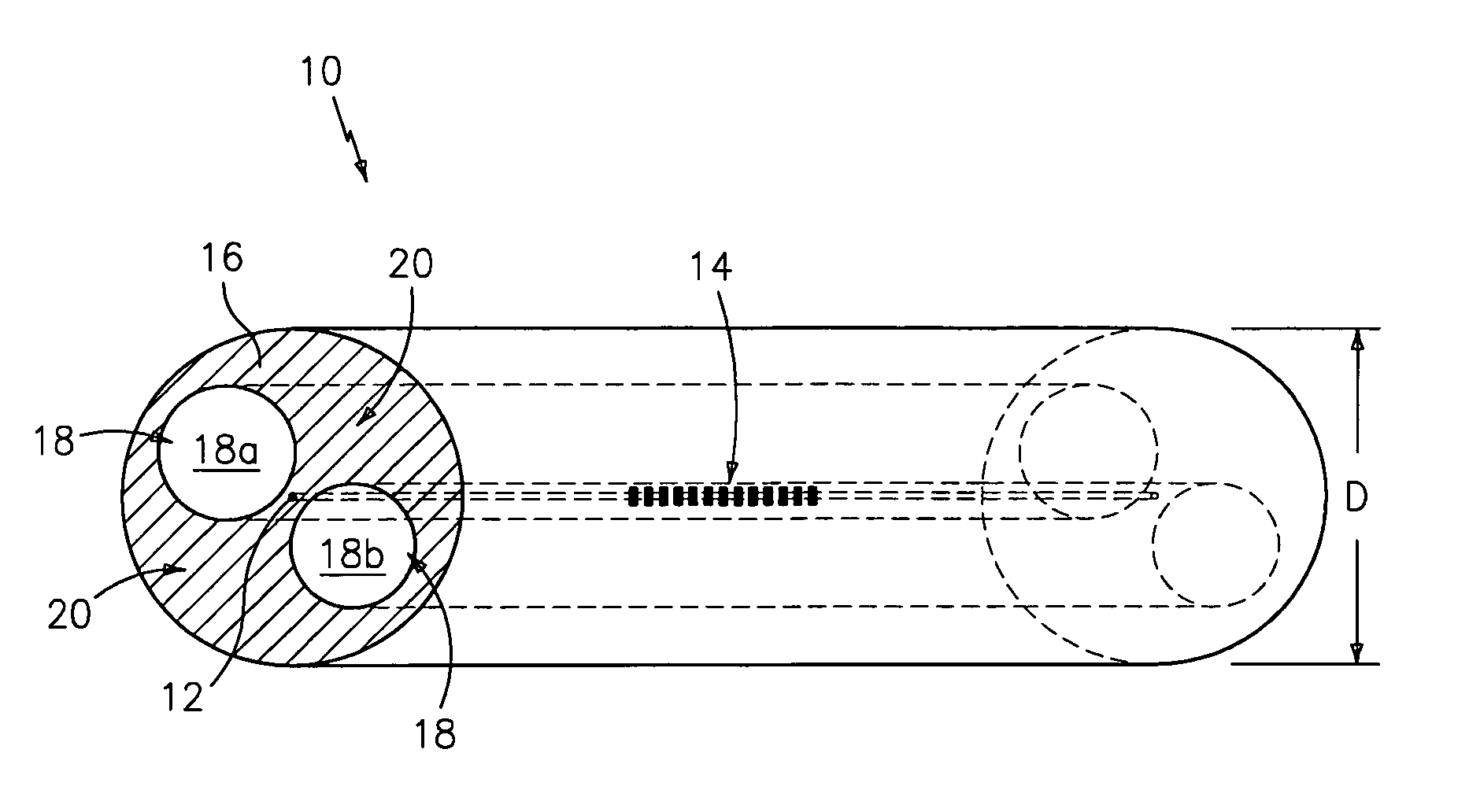
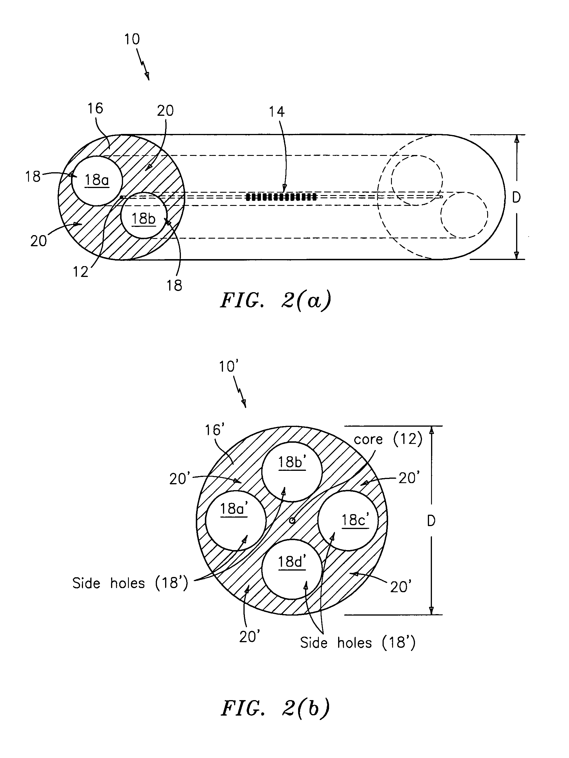
Image

Examples
Embodiment Construction
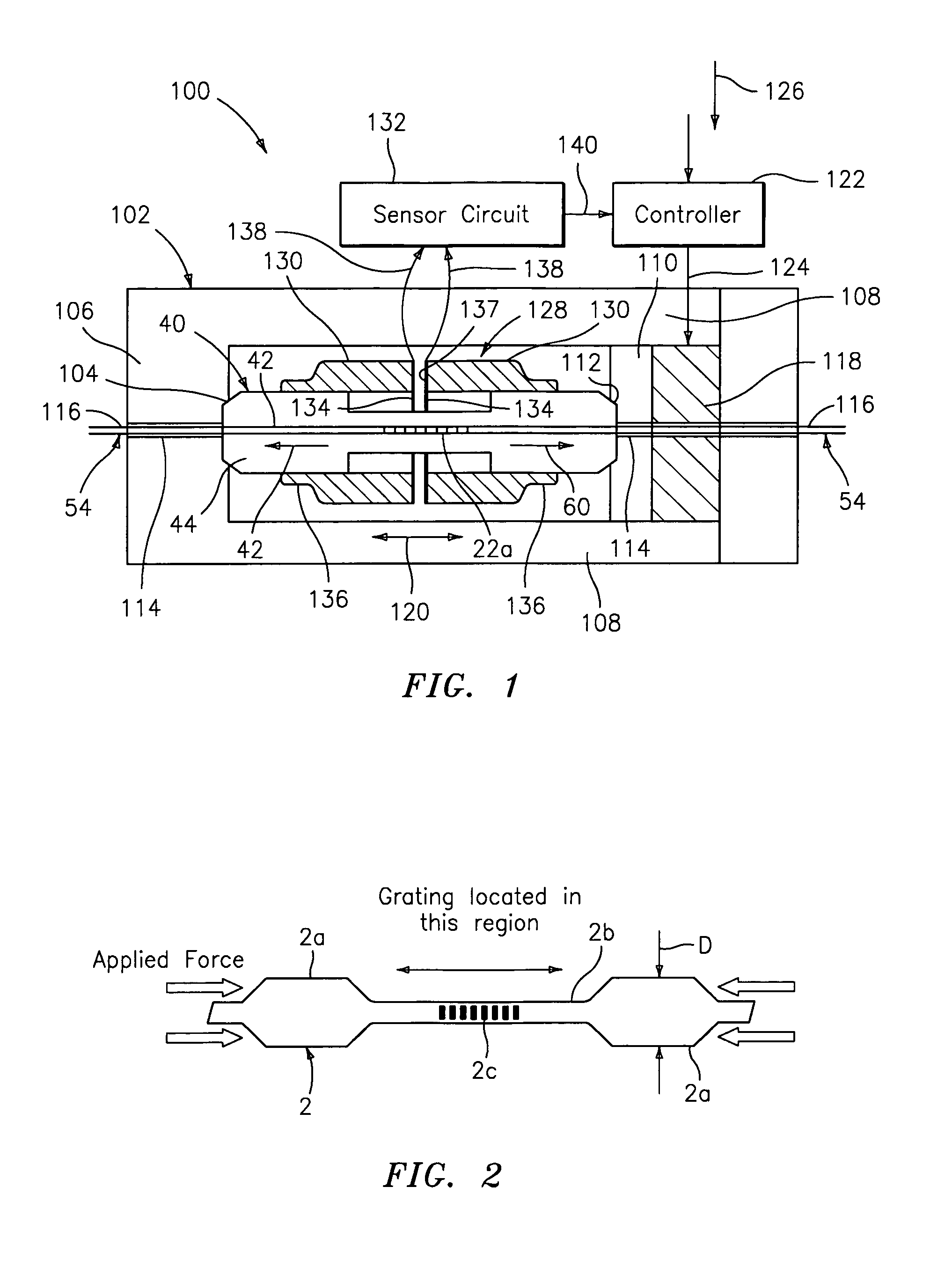
FIG. 1: Compression Tuning and Position Feedback Control
[0037]FIG. 1 shows a tunable optical filter 100 that compresses axially a large diameter optical waveguide 40 using a non-optical closed control loop. The tunable optical filter 100 may be adapted for tuning any of the large diameter optical waveguides discussed below, and is similar to that disclosed in co-pending U.S. Patent Application Ser. No. 09 / 707,084 entitled “Compression-Tuned Bragg Grating and Laser”, application Ser. No. 09 / 205,845, application Ser. no. 455,865, filed Dec. 6, 1999, application Ser. No. 10 / 146,773, filed May 16, 2000, as well as the aforementioned co-pending U.S. patent application Ser. No. 09 / 455,868, all which are hereby incorporated herein by reference in their entirety. The tunable optical filter 100 operates as follows:
[0038]The tunable optical filter 100 compresses axially the large diameter optical waveguide 40 within a housing 102. One end of the large diameter optical waveguide 40 is pressed ...
PUM
| Property | Measurement | Unit |
|---|---|---|
| Length | aaaaa | aaaaa |
| Diameter | aaaaa | aaaaa |
| Strength | aaaaa | aaaaa |
Abstract
Description
Claims
Application Information