Updating high speed parallel I/O interfaces based on counters

a counter and high-speed technology, applied in the direction of electronic circuit testing, measurement devices, instruments, etc., can solve the problem of clock signal degraded transmission

Inactive Publication Date: 2006-06-13
ORACLE INT CORP
View PDF26 Cites 10 Cited by
  • Summary
  • Abstract
  • Description
  • Claims
  • Application Information

AI Technical Summary

Problems solved by technology

Also, the transmission of the clock signal may degrade as it travels from its transmission point.

Method used


Image

  • Updating high speed parallel I/O interfaces based on counters
  • Updating high speed parallel I/O interfaces based on counters
  • Updating high speed parallel I/O interfaces based on counters

Examples


Embodiment Construction

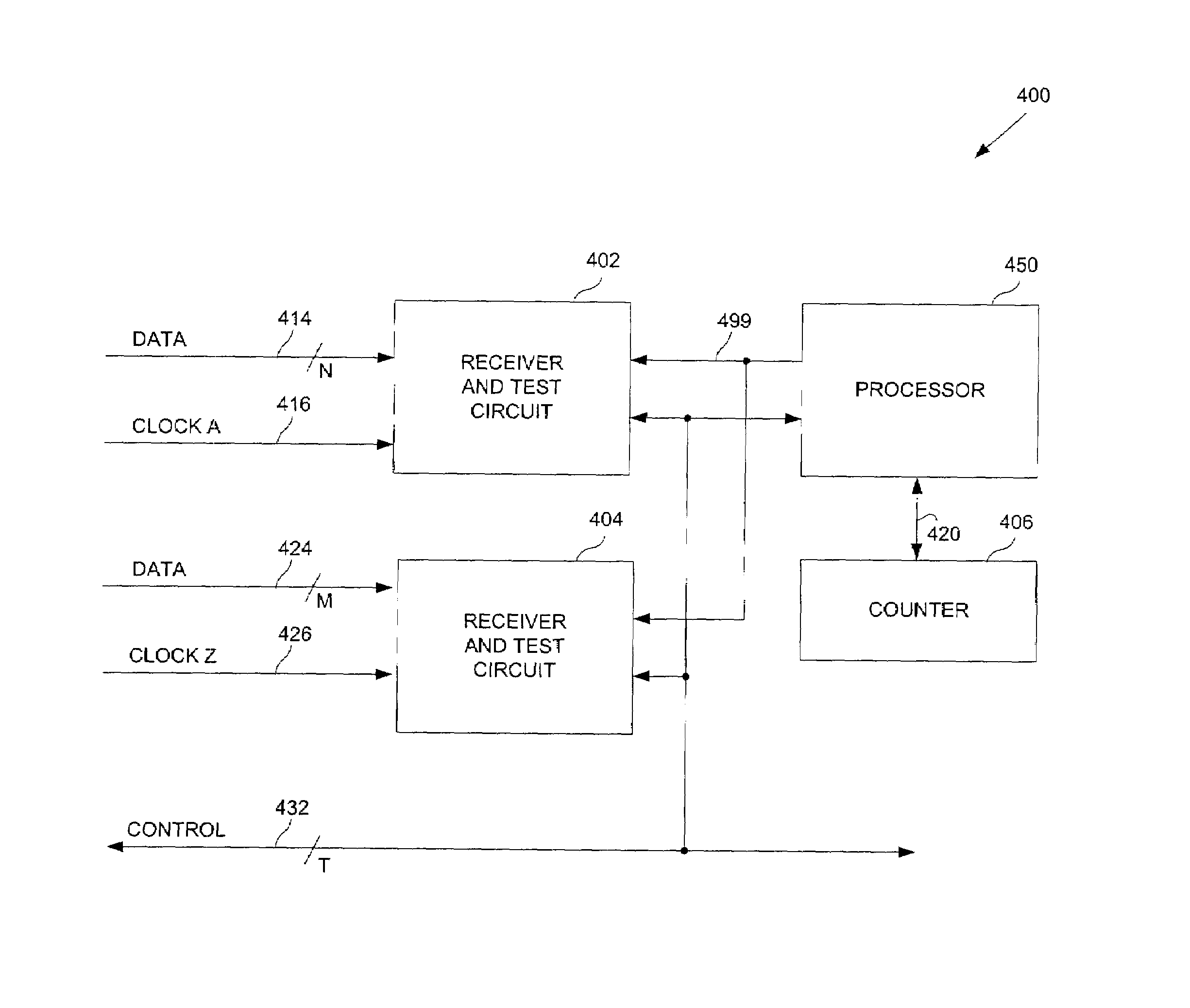
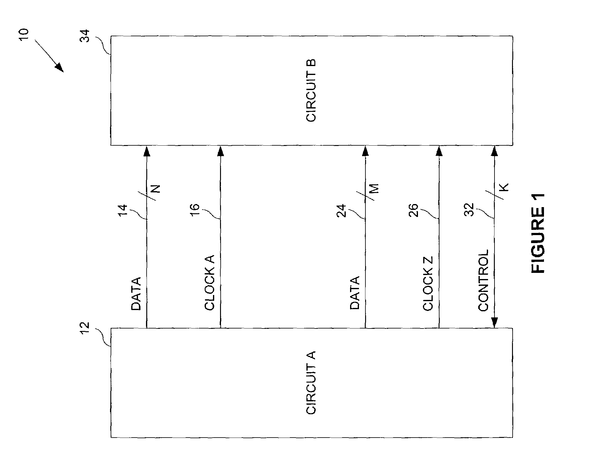
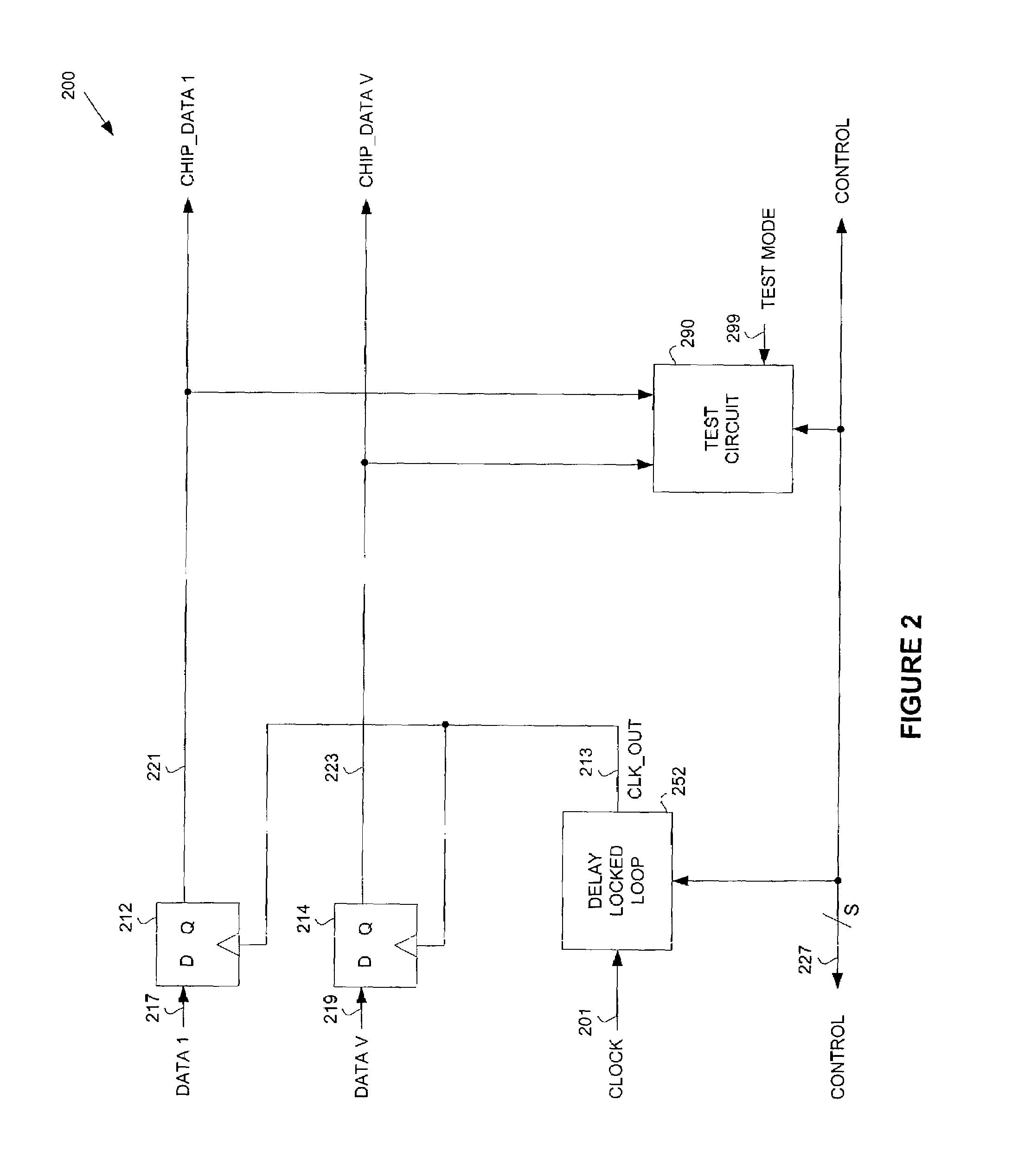
[0024]Embodiments of the present invention relate to a communication system having at least one link. The link includes at least one data line and a clock line. On the link, a data signal on the at least one data line is transmitted along with a clock signal on the clock signal line (i.e., source synchronous transmission). A test circuit connected to the link adjusts the timing of a delayed copy of the clock signal to determine when the data signal should be latched. A predetermined test pattern is used to identify which bits are not correctly latched.

[0025]Embodiments of the present invention use at least one counter to determine when the delay of the clock signal is tested and updated. The at least one counter indicates to a processor that a predetermined interval has elapsed. In the prior art, the testing of a link is performed only during the power-on reset of the integrated circuit. In the present invention, the at least one counter is arranged such that a link may be tested pe...


PUM


Abstract

A technique for adjusting a communication system involves a link, where the link includes a data line arranged to transmit a data signal and a clock line adapted to transmit a clock signal. The technique uses one or more counters to test the transmission across the link. Dependent on one or more of these counters, a test circuit, connected to the link, compares a known test pattern signal to a latched test pattern signal transmitted on the data line. The test circuit includes an adjustment circuit arranged to generate an adjustable clock signal from the clock signal, where the adjustable clock signal determines when to latch the transmitted test pattern signal The test circuit adjusts a timing of the adjustable clock signal relative to the data signal of the link.

Description

BACKGROUND OF INVENTION[0001]As the frequencies of modern computers continue to increase, the need to rapidly transmit data between chip interfaces also increases. To accurately receive data, a clock signal is often transmitted to help recover the data. The clock signal determines when the data signal should be sampled by a receiver's circuits.[0002]The transmitted clock signal may transition at the beginning of the time the data is valid; however, the receiver's circuits should latch the data during the middle of the time the data is valid. Also, the transmission of the clock signal may degrade as it travels from its transmission point. In both circumstances, a delay locked loop, or DLL, can regenerate a copy of the clock signal at a fixed phase shift from the original.[0003]FIG. 1 shows a block diagram of a typical communication system (10). The communication system (10) includes multiple links. Each link may include multiple data lines and an associated clock line. Data lines (14...

Claims


Application Information

Patent Timeline
Patent Type & Authority Patents(United States)
IPC IPC(8): G01R31/28G06F11/24
CPCG06F11/24
Inventor GAUTHIER, CLAUDE R.ROY, ANINDA K.AMICK, BRIAN W.LIU, DEAN
Owner ORACLE INT CORP
Why Eureka
Try Eureka