Breathing assistance apparatus

a technology of breathing assistance and apparatus, applied in the field of valves, can solve the problems of ineffective reverse of normal breathing function, difficulty in initial use of cpap, and ineffectiveness of existing devices

Inactive Publication Date: 2006-06-20
FISHER & PAYKEL HEALTHCARE LTD
View PDF19 Cites 123 Cited by
  • Summary
  • Abstract
  • Description
  • Claims
  • Application Information

AI Technical Summary

Benefits of technology

[0009]It is an object of the present invention to provide a valve for a respiratory breathing circuit which will obviate the above disadvantage or will at least provide healthcare providers with a useful choice.

Problems solved by technology

One disadvantage of CPAP treatment is that it effectively reverses the normal breathing function.
Since normal breathing requires the exact opposite, the use of CPAP is sometimes difficult initially.
However to some degree these existing devices are still somewhat ineffective.
Also in some cases these apparatus include a bulky face mask and strapping which may be uncomfortable for the user.

Method used


Image

  • Breathing assistance apparatus
  • Breathing assistance apparatus
  • Breathing assistance apparatus

Examples


Embodiment Construction

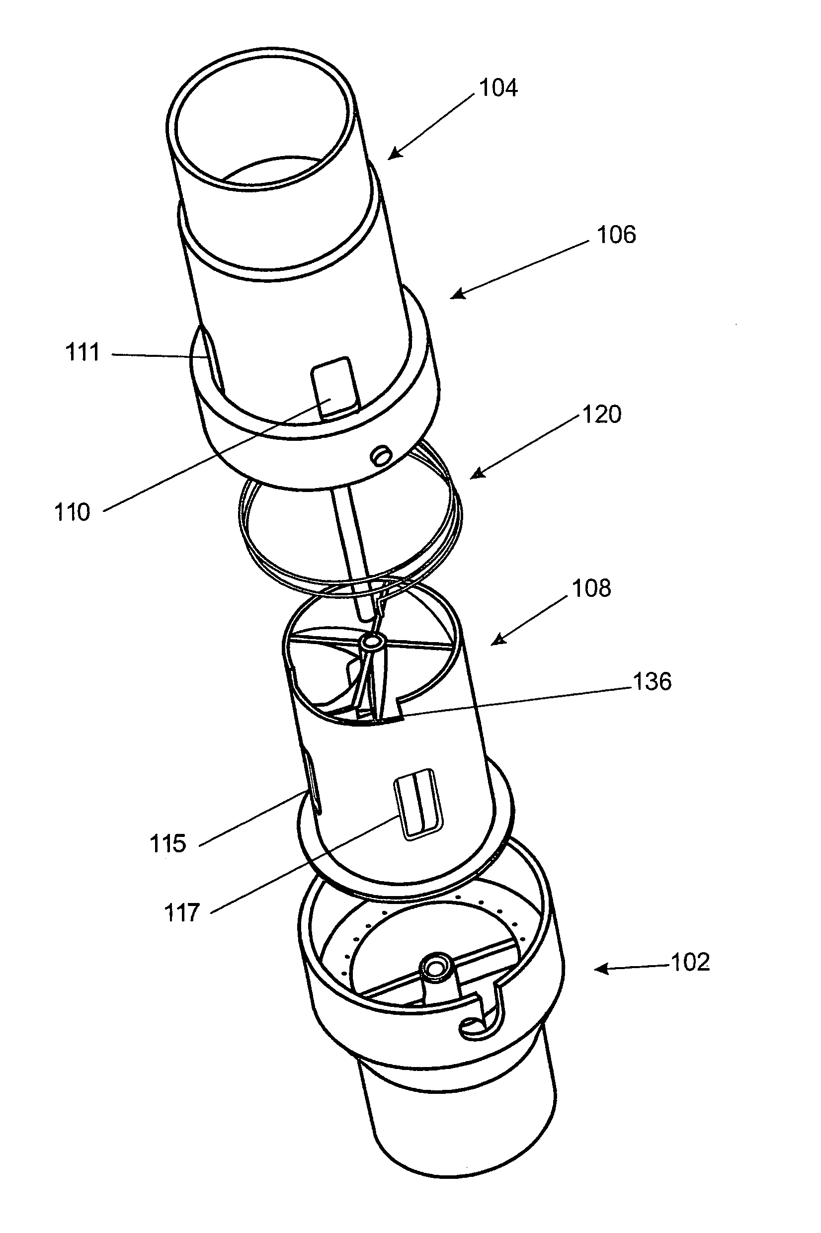
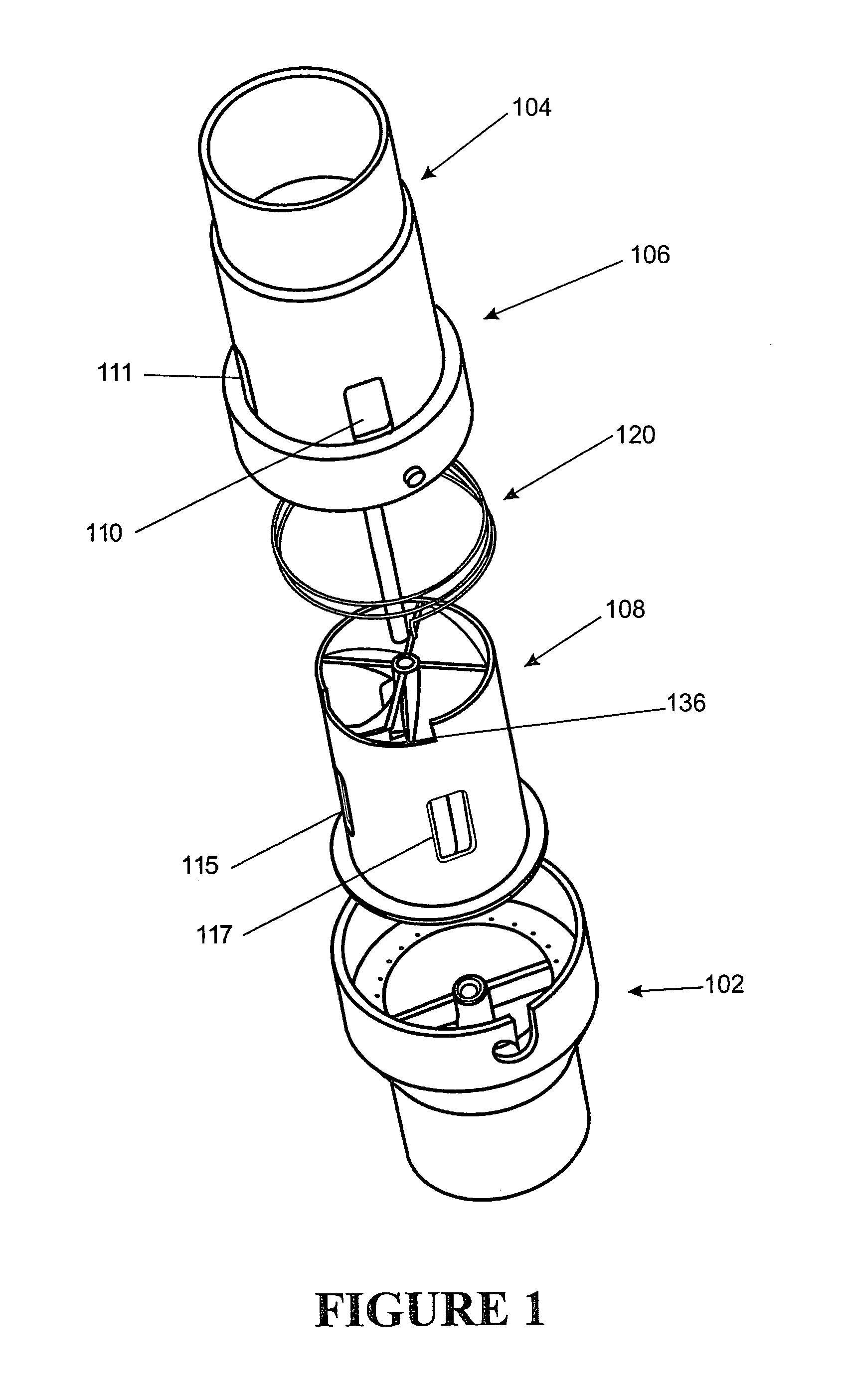
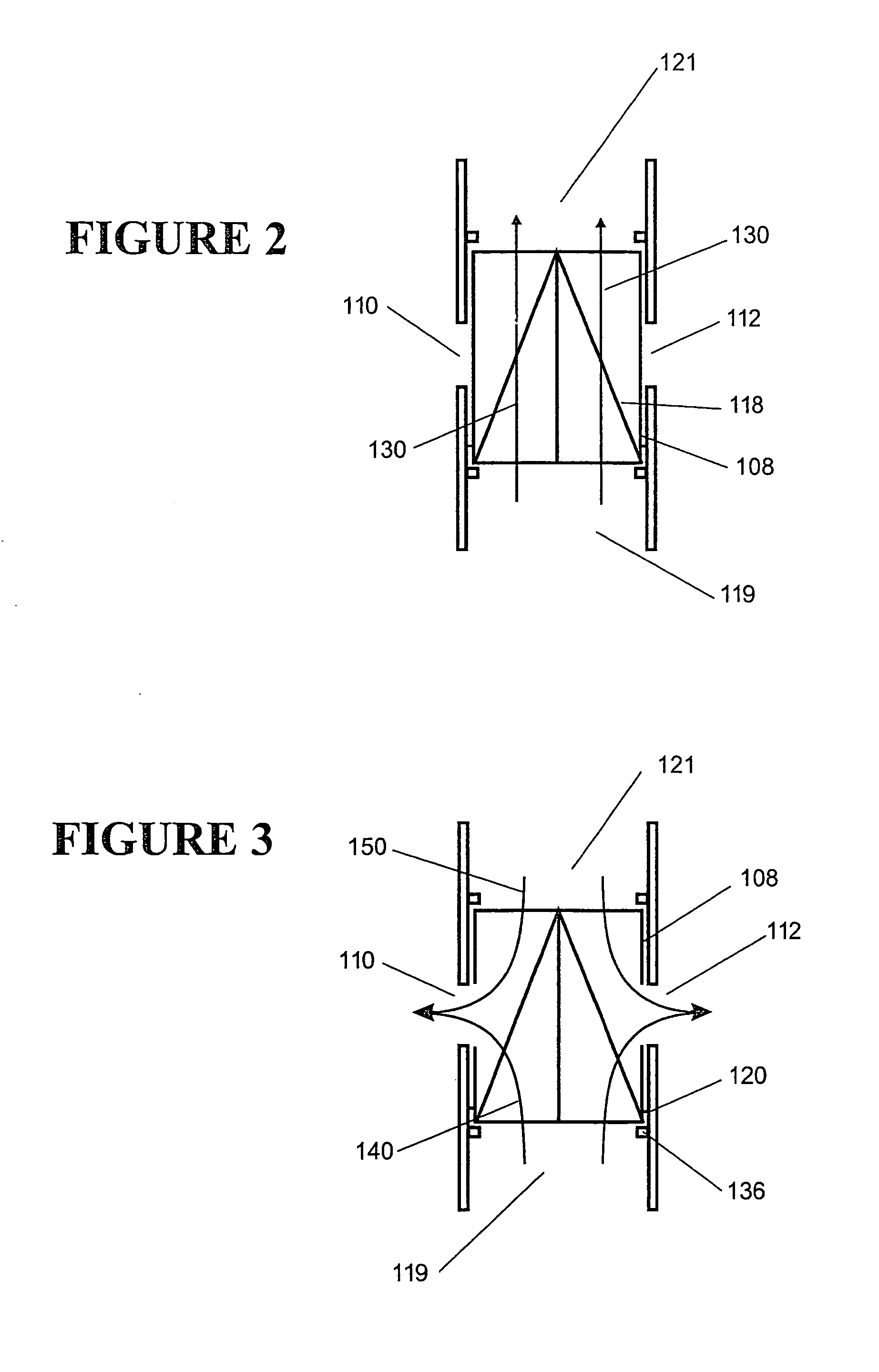
[0042]The present invention attempts to provide a simple to manufacture device which attempts to improve comfort levels for a user undergoing CPAP therapy. This is done by providing a three-way valve in the conduit between the respirator and the patient which allows both gases to flow to the patient and exhalations to be expelled to flow through the same conduit. This makes exhaling easier for the user, without the need for additional apparatus to be worn by the user. If the gases supplied to the user are to be humidified, the valve is positioned between the respirator and the humidifier, i.e. upstream of the humidifier. The contents of copending U.S. application Ser. No. 09 / 662203 are incorporated herein by reference.

[0043]Referring now to FIG. 1, we see the valve in more detail. The valve body 100 has two ends 102, 104 adapted for connection to a typical respiratory conduit and an enlarged centre section 106 which houses the rotatably moveable valve member 108. The centre section ...


PUM


Abstract

A valve for use in a CPAP system or any stem at a pressure above ambient which vents the pressurised gases from the blower during expiration. Due to the pressure-flow characteristics of the blower this results in the patient having a much lower airway pressure during expiration making breathing easier. The valve includes a movable member which blocks flow from the blower to the patient during exhalation and vents externally. During inhalation gases flow normally from the blower to the patient. Also disclosed is a further application as an antiasphyxia.

Description

[0001]This application is a Continuation-In-Part of U.S. patent application Ser. No. 09 / 662,203, filed on Sep. 14, 2000.FIELD OF INVENTION[0002]This invention relates to valves particularly through not solely for inclusion in the breathing circuit of a respirator.SUMMARY OF THE PRIOR ART[0003]A medical breathing circuit such as might be used in a Continuous Positive Airway Pressure Respirator (CPAP) includes an inspiratory gases tube which has one end thereof connected to the patient through an interface. For example through an endotracheal breathing tube extending into the trachea and ending just above the lungs. The other end thereof is connected to a respirator providing pressurised gases. The connection to the respirator may be direct or a self contained humidifier may be interposed.[0004]One disadvantage of CPAP treatment is that it effectively reverses the normal breathing function. The patient has to relax to breath in and requires effort to breath out. Since normal breathing...

Claims


Application Information

Patent Timeline
Patent Type & Authority Patents(United States)
IPC IPC(8): A62B9/02A61M16/06A61M16/20
CPCA61M16/208A61M16/06
Inventor SHAHBAZPOUR, MEHDITROUSDELL, MICHAEL JOHN BLOODNIGHTINGALE, CHRIS EARLMCAULEY, ALASTAIR EDWINSHOTBOLT, AIDAN MARK
Owner FISHER & PAYKEL HEALTHCARE LTD
Why Eureka
Try Eureka