Baggage tag and method for using baggage tag
a technology for baggage tags and bags, applied in the field of baggage tags, can solve the problems of difficult to read the printed bar code, difficult to record a large amount of information, rough surface of thermal recording layers, etc., and achieve the effect of preventing problems due to defective recording
- Summary
- Abstract
- Description
- Claims
- Application Information
AI Technical Summary
Benefits of technology
Problems solved by technology
Method used
Image

Examples
example 1
(1) Manufacture of Circuit Element
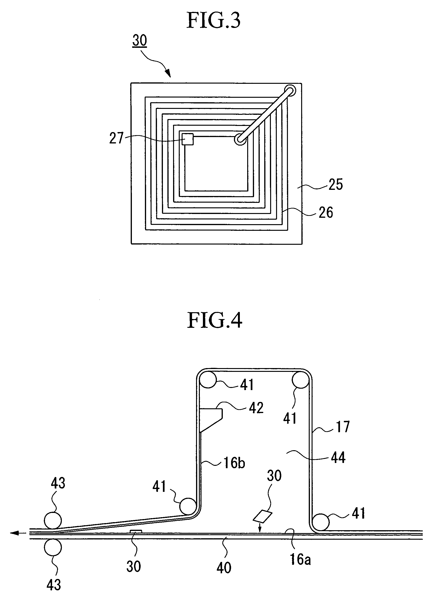
[0110]A copper foil antenna circuit having a thickness of 35 μm was formed on a PET film of 40 μm thickness (trade name: UP2W, a product of Teijin Du Pont Co.) using an etching method.
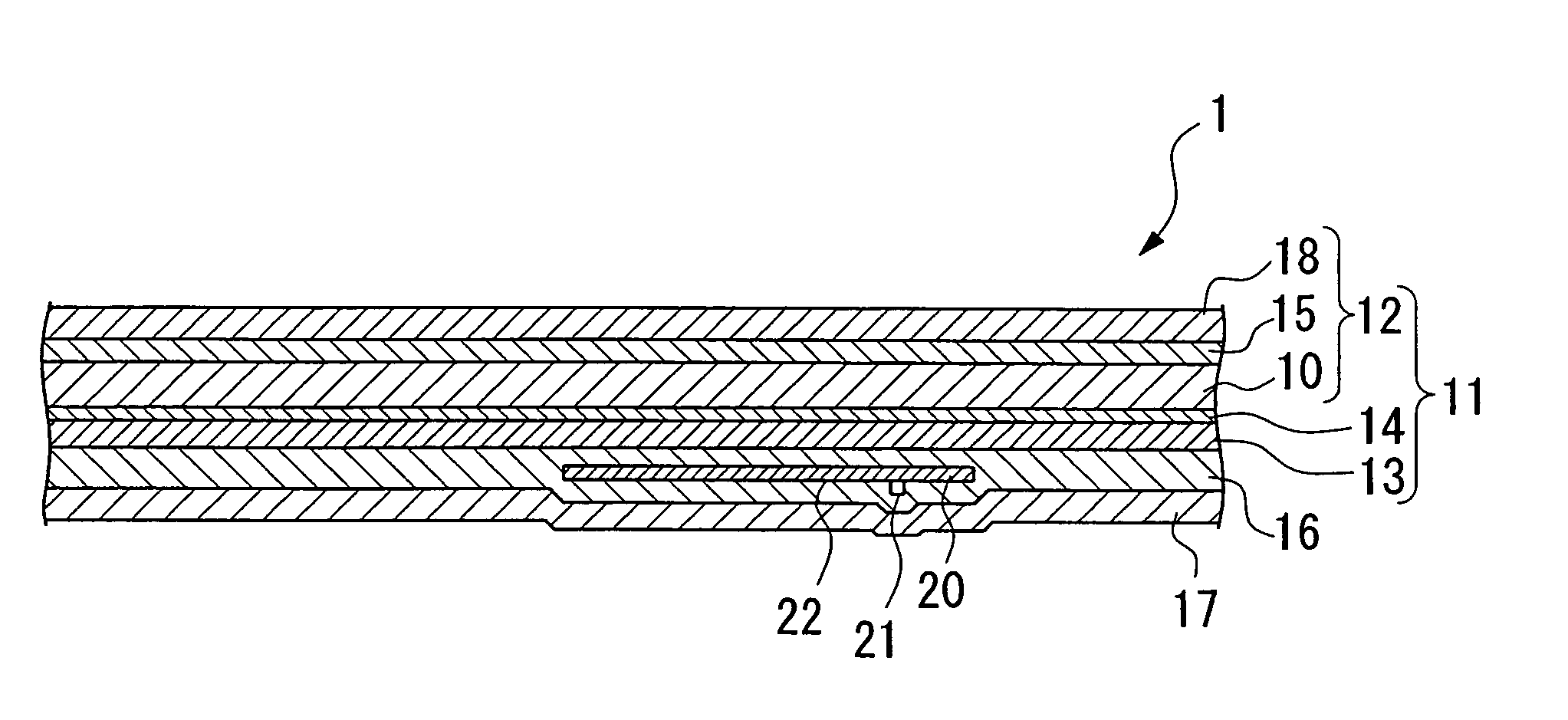
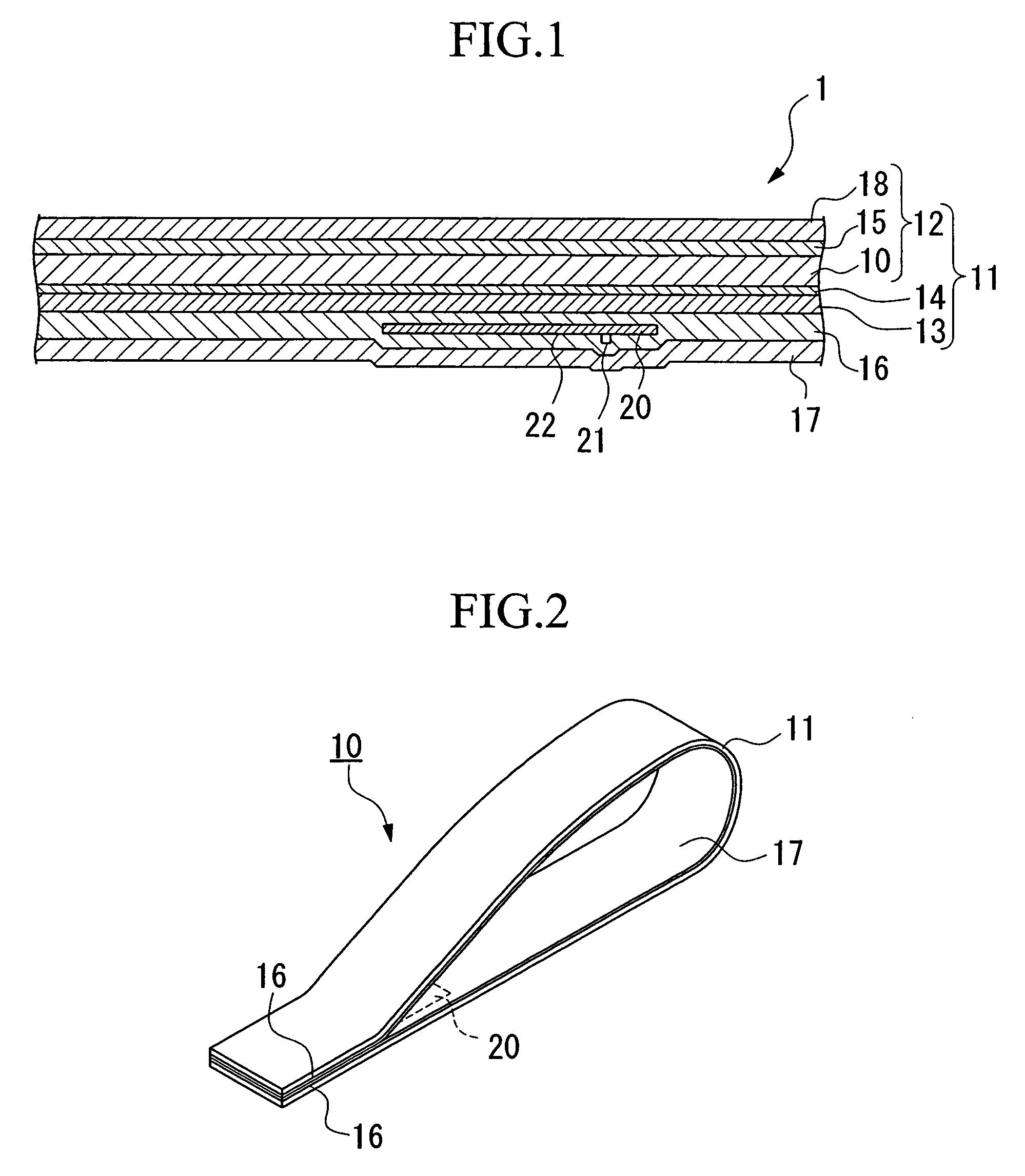
[0111]Also, an IC chip (4 mm×4 mm, 100 μm thickness) provided with a connecting bump of 20 μm height was connected to a terminal of the above-mentioned antenna circuit using an oriented conduction film adhesive of 50 μm thickness (trade name: FC 161A, a product of Hitachi Chemical Co. Ltd.) to obtain a circuit element (hereinafter also referred to as an inlet).
(2) Preparation of Solutions A–D
[0112]The following components were mixed with stirring to obtain the solution A:
[0113]
calcined clay (oil absorbing amount: 110 ml / 100 g)100 parts40% aqueous solution of sodium polyacrylate 1 partpolyvinyl alcohol (10% aqueous solution)200 partswater100 parts
[0114]Note that calcined clay was ground until the average particle size thereof became 1.0 μm using a sand mill in the prepa...
example 2
[0131]A laminate was manufactured in the same manner as in Example 1 except that a synthesized polypropylene paper of 80 μm thickness (trade name: Yupo CFG80, a product of Yupo Corporation) was used instead of the polypropylene film of 40 μm thickness. The Clark degree of the laminate in the recording direction of the recording paper was 60.
[0132]Using the same method as in Example 1 except that the above laminate was used, a tag for airline baggage having an IC chip between the laminate and the backside protection sheet was obtained. The Elmendorf tear strength of the tag for airline baggage in the CD direction was 835 mN (85 g). When the print test was performed on the obtained tag for airline baggage, the evaluation result was ranked A, and a required printing quality was obtained without generating any print mackle. Also, as for the communication ability test, a result of 10 out of 10 was obtained, and hence it showed an excellent communication ability.
examples 3 – 7
Examples 3–7, Comparative Examples 5 and 6
(1) Manufacture of Laminate
[0152]A laminate was formed in the same manner as in Example. 1 except that the type of paper described in the thermal paper section in Table 1 (upper: type of paper; middle: thickness of paper; and lower: thickness of paper after being provided with an undercoating layer, a thermal layer, and a protection layer) and the film described in Table 1 (upper: type; and lower: thickness) were used and bound using a binder (the same binder as in Example 1) of an amount (upper: application amount; and lower: thickness) described in the binding layer section in Table 1. The Clark degree of each of the obtained laminate in the recording direction of the recording layer was shown in Table 1.
(2) Manufacture of Tag for Airline Baggage
[0153]A tag for airline baggage of 250 μm thickness was produced in the same manner as in Example 1 except that the above-mentioned laminate, a base material of release sheet (in the release paper ...
PUM
| Property | Measurement | Unit |
|---|---|---|
| thickness | aaaaa | aaaaa |
| size | aaaaa | aaaaa |
| thickness | aaaaa | aaaaa |
Abstract
Description
Claims
Application Information
 - R&D
- Intellectual Property
- Life Sciences
- Materials
- Tech Scout
- Unparalleled Data Quality
- Higher Quality Content
- 60% Fewer Hallucinations
Browse by: Latest US Patents, China's latest patents, Technical Efficacy Thesaurus, Application Domain, Technology Topic, Popular Technical Reports.
© 2025 PatSnap. All rights reserved.Legal|Privacy policy|Modern Slavery Act Transparency Statement|Sitemap|About US| Contact US: help@patsnap.com