
Method for calibrating and enhancing flaw detection of an acoustic thermography system

a technology of acoustic thermography and flaw detection, applied in the field of acoustic thermography, can solve the problems of insufficient heat generation of open voids or cracks under known acoustic thermography techniques, high cost of devices, and time-consuming deployment in industrial applications, and achieve the effect of enhancing the ability of an acoustic thermography system

Inactive Publication Date: 2006-06-20
SIEMENS ENERGY INC
View PDF15 Cites 20 Cited by
  • Summary
  • Abstract
  • Description
  • Claims
  • Application Information

AI Technical Summary

Benefits of technology

"The present invention provides a method for calibrating an acoustic thermography system and enhancing its ability to detect flaws in a specimen. This is achieved by applying a material to the specimen that is thermally responsive to acoustic energy transmitted to it by the acoustic thermography system. The thermal response of the material and the specimen is processed to determine the level of acoustic energy and the vibration mode characteristics that meet the desired inspection requirements. This method may be useful for detecting flaws that may not be typically responsive to acoustic thermography inspection."

Problems solved by technology

Although accelerometers and laser-based vibrometers are accurate devices for determining the amount of acoustic energy applied to the specimen, undesirably, such devices tend to be expensive, cumbersome, and time-consuming for deployment in industrial applications.
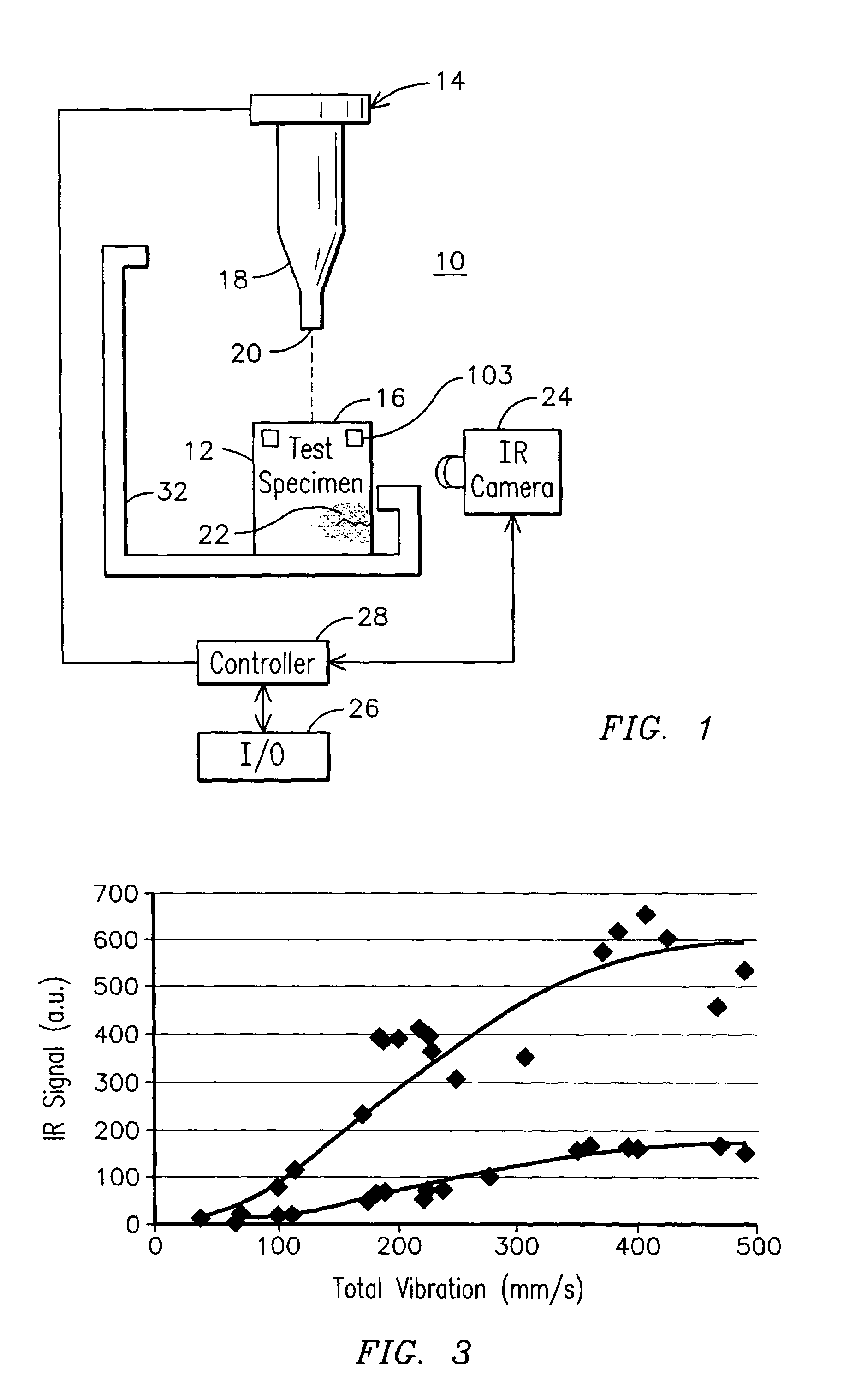
In known acoustic thermography techniques, it has been observed that just relatively tight flaws appropriately heat up to become detectable.
That is, relatively wide, open voids or cracks may not sufficiently heat up under known acoustic thermography techniques.

Method used


Image

  • Method for calibrating and enhancing flaw detection of an acoustic thermography system
  • Method for calibrating and enhancing flaw detection of an acoustic thermography system
  • Method for calibrating and enhancing flaw detection of an acoustic thermography system

Examples


Embodiment Construction

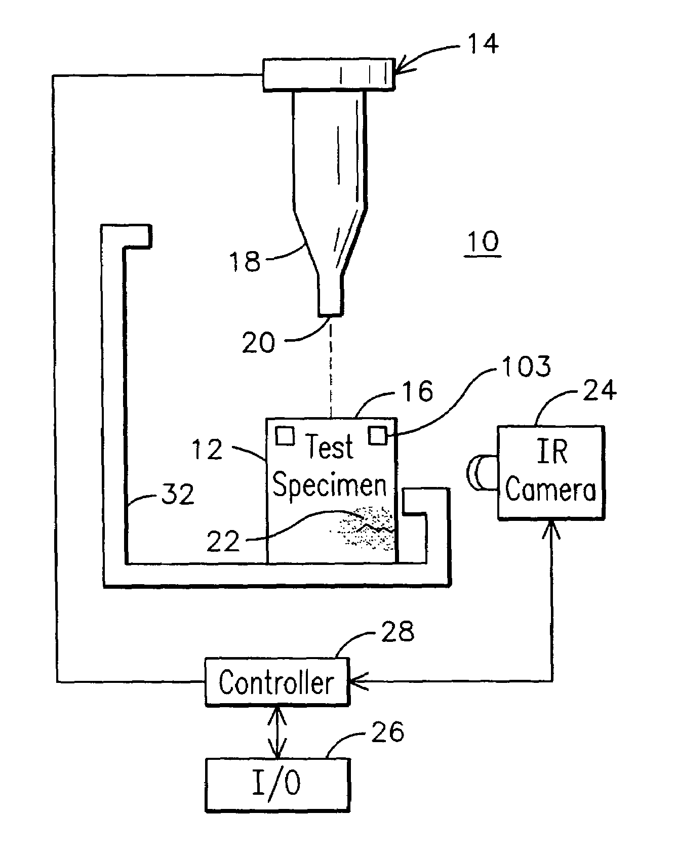
[0013]An exemplary system 10 used for nondestructive testing of a test specimen 12 is illustrated in schematic form in FIG. 1. The system includes an acoustic energy source 14 for delivering acoustic energy to a surface 16 of the specimen 12, as the specimen is held in a fixture 32. The type of specimens that may be inspected may be the type where a failure could cause operational issues, for example, heat exchanger tubes and other metal components used in nuclear and other types of steam generators, power generation gas turbines and steam turbines, electrical generators, aircraft parts, aerospace, automotive, manufacturing, electronics, marine, construction parts and the like.

[0014]The acoustic energy source 14 may be an ultrasonic piezoelectric device. The acoustic energy may be transferred through a probe tip such as horn 18 having a face 20 for making contact with specimen surface 16. Vibrations within the specimen 12 will cause localized heating in an area 22 surrounding a crac...


PUM

PropertyMeasurementUnit
wavelengthaaaaaaaaaa
displacementaaaaaaaaaa
acoustic energyaaaaaaaaaa

Abstract

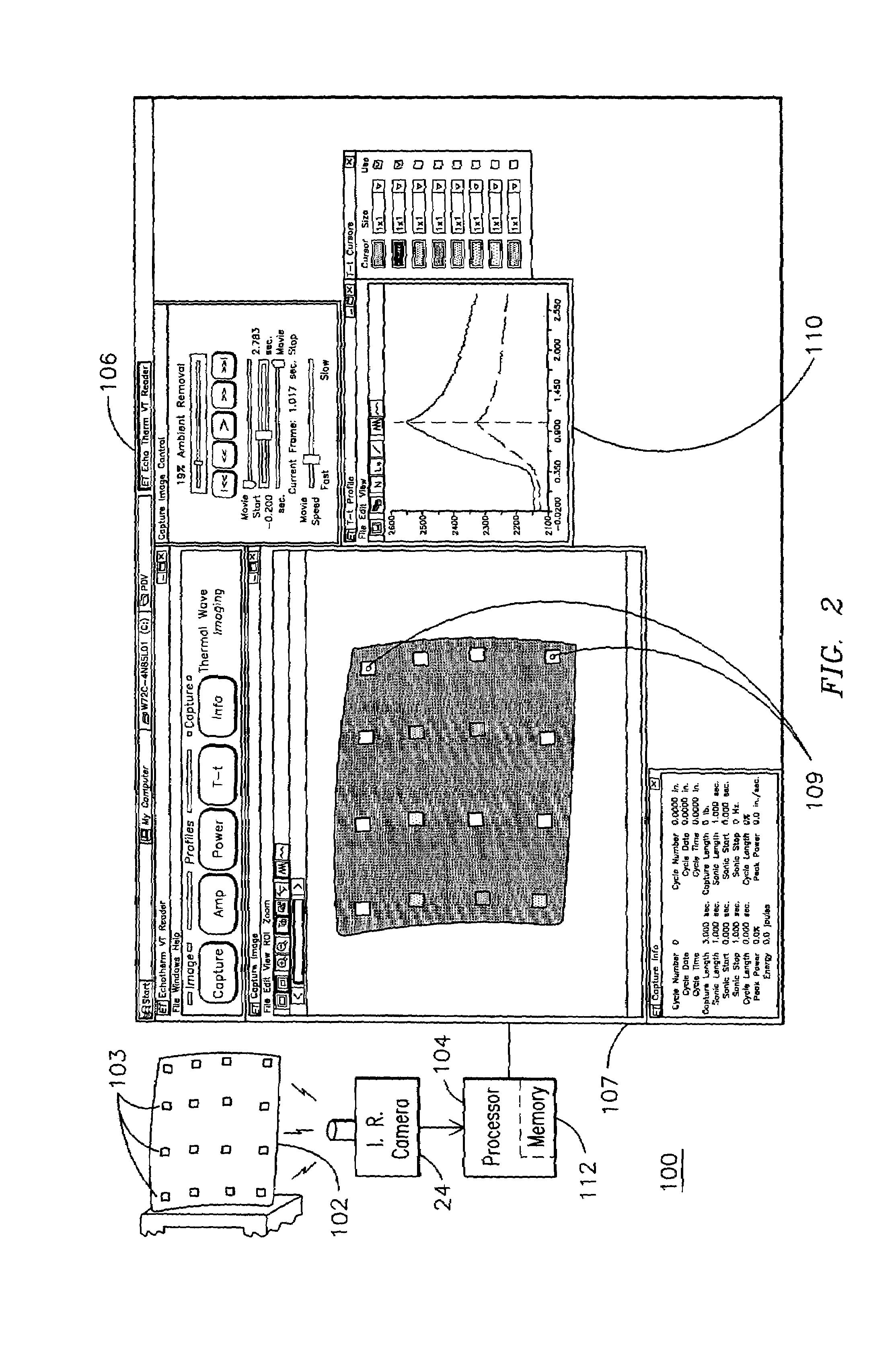
A method and apparatus for calibrating an acoustic thermography system 10 and / or enhancing the flaw detection abilities of such a system is provided. The method allows applying a material (e.g., 103) to a specimen 12 undergoing acoustic thermography inspection. The material is thermally responsive to acoustic energy transmitted to the specimen by the acoustic thermography system. In one aspect thereof, a thermal response of the material applied to the specimen when subjected to acoustic energy is processed to determine whether the level of acoustic energy applied by the acoustic thermographic system appropriately meets a desired amount of acoustic energy for inspecting the specimen. In another aspect thereof, the thermal response of the specimen in combination with the applied material may be processed to determine whether certain types of flaws (e.g., relatively wide flaws) are actually present in the specimen or to enhance the detectability of other flaws that would only faintly show up on the infrared images.

Description

[0001]This application is a Continuation-In-Part of U.S. application Ser. No. 10 / 243,009 filed Sep. 13, 2002.FIELD OF THE INVENTION[0002]This invention relates generally to the field of acoustic thermography and more particularly to techniques for calibrating and enhancing flaw detection of an acoustic thermography system.BACKGROUND OF THE INVENTION[0003]There are many known techniques for nondestructively examining a test specimen, such as a turbine blade. Many of these techniques involve introducing energy into the specimen and detecting a modified form of that energy as it leaves the specimen. For example, it is known to apply X-ray, ultrasonic, magnetic, or heat energy into a test specimen and to detect flaws in the specimen as perturbations in the respective energy pattern as it returns from the specimen.[0004]Acoustic thermography is one such form of nondestructive examination that involves the application of acoustic energy to a test specimen and the measurement of heat energ...

Claims


Application Information

Patent Timeline
Patent Type & Authority Patents(United States)
IPC IPC(8): G01N21/70G01N25/72G01N29/22G01N29/24
CPCG01N25/72G01N29/2418G01N29/228G01N2291/02881
Inventor ROTHENFUSSER, MAXHOMMA, CHRISTIANZOMBO, PAUL JOHNVONA, PAUL D.SHANNON, ROBERT E.
Owner SIEMENS ENERGY INC
Learn More