
LCD with alignment layer having multiple alignments depending on color

a technology of lcd and alignment layer, which is applied in non-linear optics, instruments, optics, etc., can solve the problems of difficulty in keeping the combination of r, g and b illuminations at a preset white-balance poin

Active Publication Date: 2006-06-20
AU OPTRONICS CORP
View PDF1 Cites 3 Cited by
  • Summary
  • Abstract
  • Description
  • Claims
  • Application Information

AI Technical Summary

Benefits of technology

"The present invention provides an LCD panel and a fabrication method that can solve the problem of separation in gamma curves. The fabrication method involves forming a first photo-alignment film on the lower panel, exposing it to show various regions related to RGB pixels, and then filling the space between the upper and lower panels with an LC layer. This LC layer is formed in accordance with the first photo-alignment film to show various transparencies and correct the RGB gamma curves of the LCD panel. The technical effect of this invention is to improve the quality of LCD panels and enhance their display performance."

Problems solved by technology

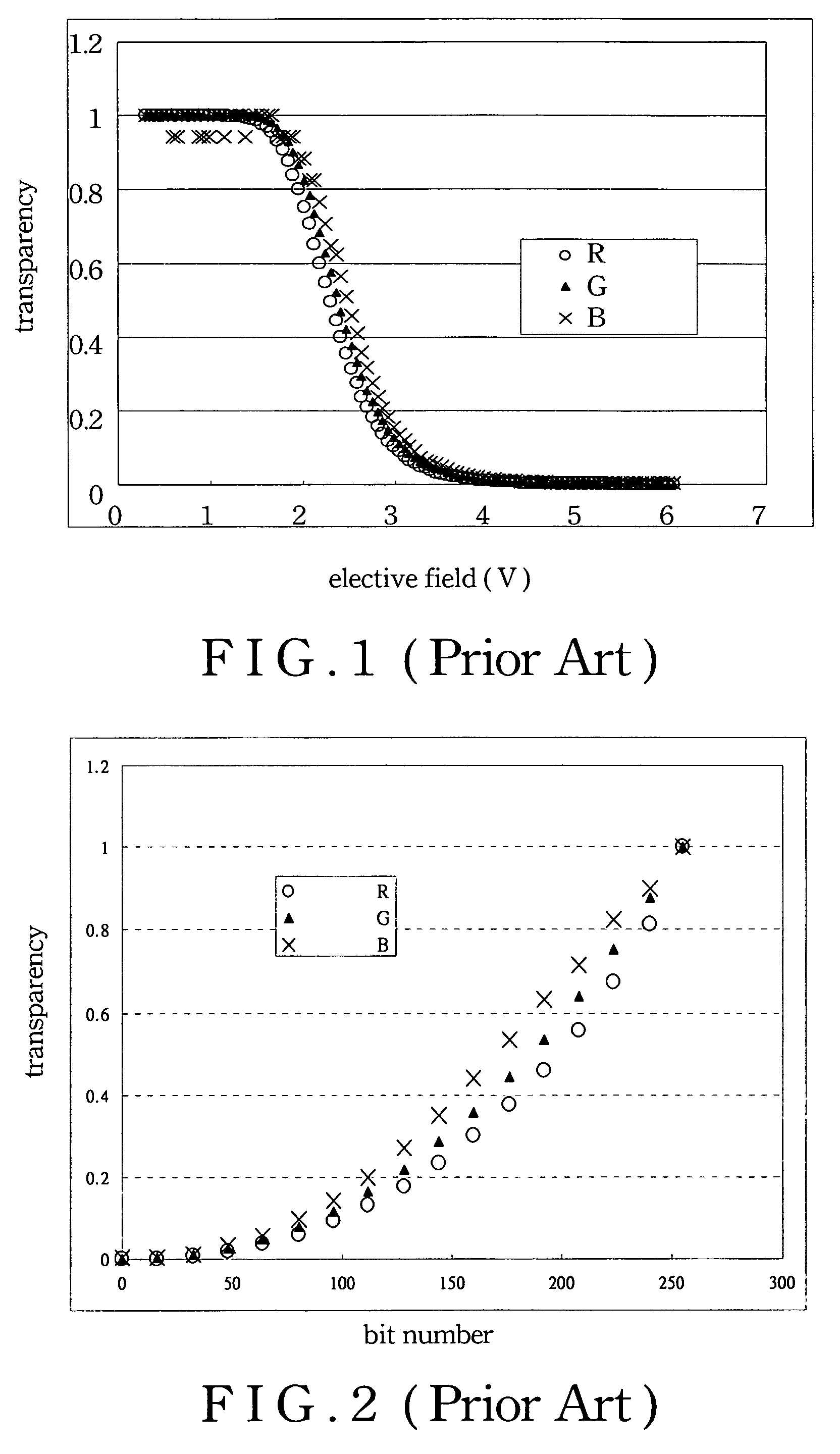
However, the RGB gamma curves of FIG. 2 are separated to each other, and therefore it would be difficult to keep the combination of R, G, and B illuminations at a preset white-balance point.

Method used


Image

  • LCD with alignment layer having multiple alignments depending on color
  • LCD with alignment layer having multiple alignments depending on color
  • LCD with alignment layer having multiple alignments depending on color

Examples


first embodiment

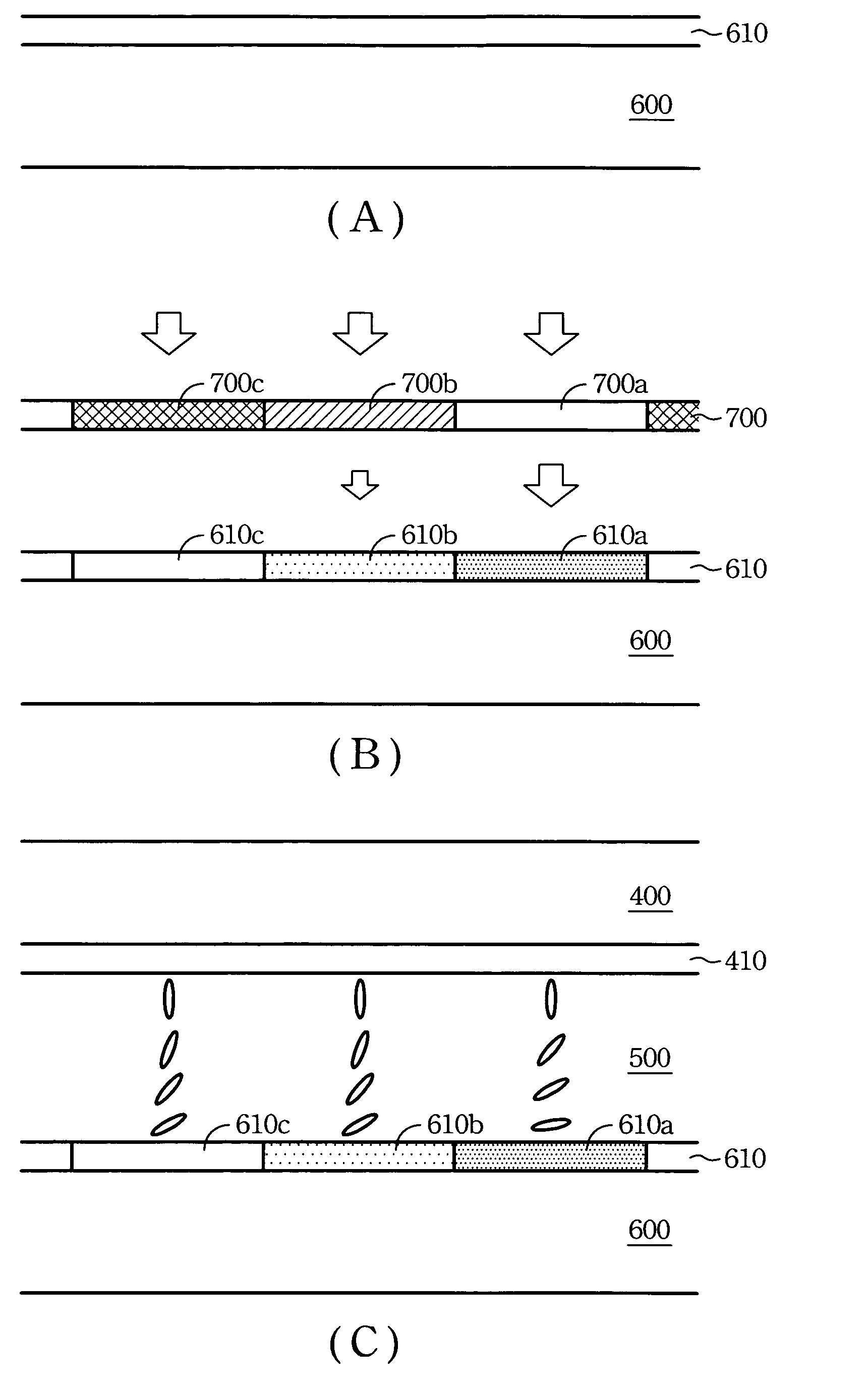
[0027]FIG. 5A to 5C shows the fabrication method to form a gamma corrected LCD panel in accordance with the present invention. Firstly, as shown in FIG. 5A, a photo-alignment material is painted on an upper surface of the lower panel 600, and then the lower panel 600 is baked to remove the solvent in the photo-alignment material to form a cured photo-alignment film 610. Afterward, as shown in FIG. 5B, the photo-alignment film 610 is exposed through a half-tone mask 700, in which the mask 700 comprises regions with different transparency levels with respect to RGB pixels. Take the half-tone mask 700 in FIG. 5B for example, region 700a with respect to R pixels has a transparency level of 100%, region 700b with respect to G pixels has a transparency level of 50%, and region 700c with respect to B pixels has a transparency level of 0%.

[0028]For example, if there needs an exposure power ratio 10:9:8 to form respectively regions 610a, 610b, 610c in the photo-alignment film 610, a blank ex...

second embodiment

[0031]FIGS. 6A and 6B shows the fabrication method to form the gamma corrected LCD panel in accordance with the present invention. In contract with the exposure process of FIG. 5B by using a half-tone mask 700, this embodiment uses two independent masks 710 and 720 with for red pixels and green pixels, respectively Firstly, as shown in FIG. 6A, the photo-alignment layer 610 is exposed through a first mask 710 to form an exposed region 610a with respect to the R pixels. Then, as shown in FIG. 6B, the photo-alignment layer 610 is exposed through a second mask 720 to form another exposed region 610b with respect to the G pixels.

[0032]For example, if there needs an exposure power ratio 10:9:8 to form regions 610a, 610b, 610c with respect to RGB pixels, a blank exposure process can be firstly carried out to expose the photo-alignment film 610 as a whole to achieve an exposure level equal to that needed for the region 610c with respect to B pixel. After the blank exposure process, the reg...


PUM

PropertyMeasurementUnit
transparencyaaaaaaaaaa

Abstract

A gamma correction LCD panel and a fabrication of the same are provided. In the method, a lower substrate is firstly painted with a photo-alignment material. An exposing step is then introduced to have the photo-alignment material absorbed different amounts of light exposure so as to create various photo-aligning effects with respect to RGB pixel devices. The lower substrate is then assembled with an upper substrate and has an LC layer inter-filled. Upon such an arrangement, the LC layers with respect to RGB illumination can be thus provided with various transparencies for further adjust the RGB gamma curves individually.

Description

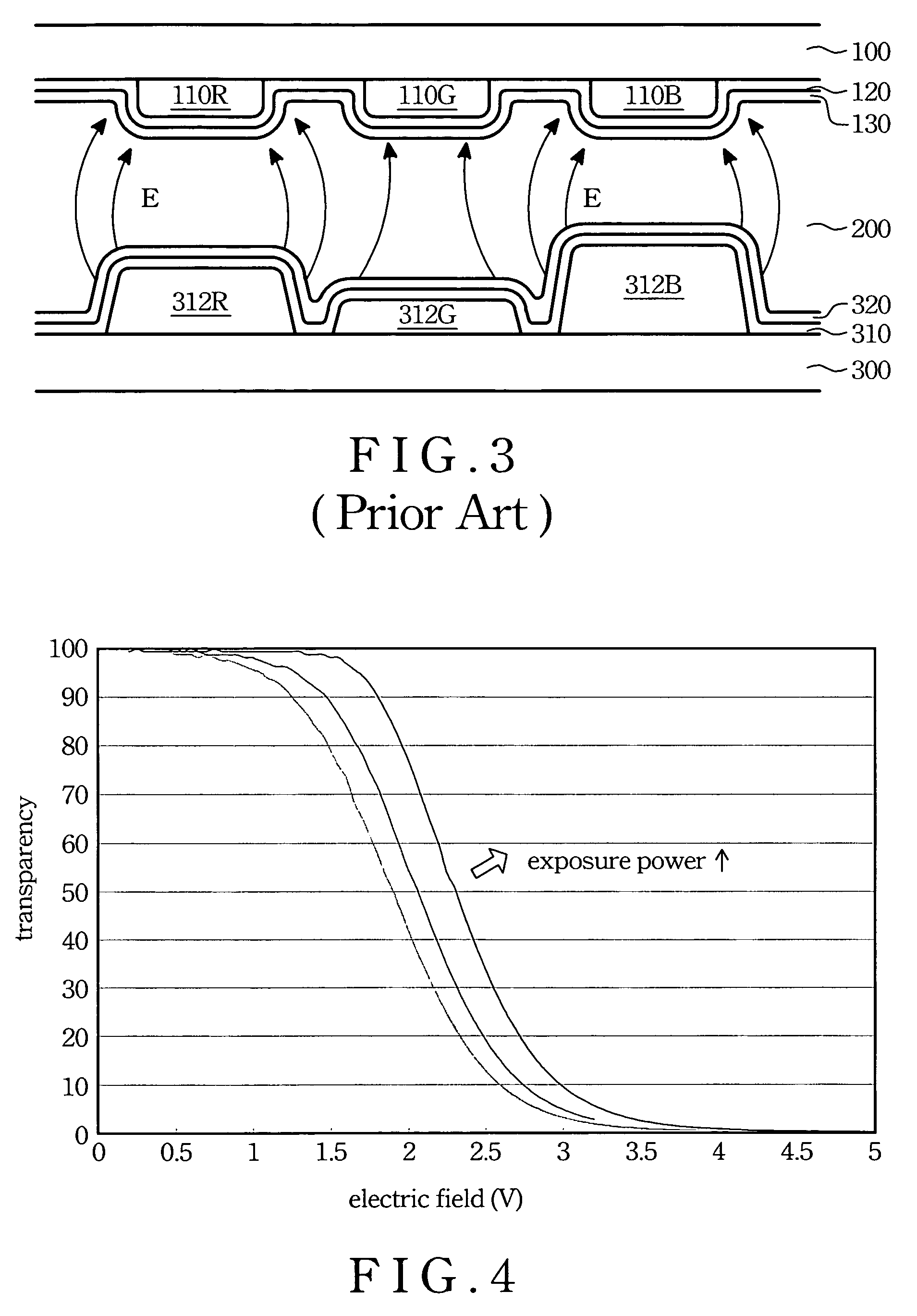
BACKGROUND OF THE INVENTION[0001](1) Field of the Invention[0002]This invention relates to a gamma corrected LCD panel, and more particularly to an LCD panel having its RGB gamma curves adjusted to a preset white-balance point. Also, the invention relates to a method for producing the aforesaid panel.[0003](2) Description of Related Art[0004]Recently, liquid crystal displays (LCD) become more popular than ever as a displaying component used in personal digital assistants (PDA), notebooks (NB), digital cameras (DC), digital videos (DV), mobile phones, etc. Due to lack of self-illumination, a cold cathode fluorescent lamp (CCFL) is required in an LCD as a backlight source. In addition, the LCD also needs a liquid crystal (LC) driving circuit to decode the input signals into corresponding LC operation voltage levels so as to adjust the transparency of RGB pixels for achieving full-color imaging.[0005]FIG. 1 depicts a typical relationship of pixel devices' transparency and the applied e...

Claims


Application Information

Patent Timeline
Patent Type & Authority Patents(United States)
IPC IPC(8): G02F1/1337G02F1/1335
CPCG02F1/133514G02F1/133516G02F2001/136236G02F2001/133761G02F1/133788G02F1/133761G02F1/136236
Inventor TUNG, JEN-LANGCHANG, HAU-YUH
Owner AU OPTRONICS CORP
Learn More