Method for fine timing acquisition

a technology of fine timing and acquisition method, applied in the direction of synchronisation signal speed/phase control, amplitude demodulation, digital transmission, etc., to achieve the effect of reducing overhead, reducing the number of bits required, and more efficient physical layer communication and networking protocols

Active Publication Date: 2010-01-26
THE BOEING CO
View PDF6 Cites 1 Cited by
  • Summary
  • Abstract
  • Description
  • Claims
  • Application Information

AI Technical Summary

Benefits of technology

[0014]One advantage of the present invention is that the system creates more efficient physical layer communications and networking protocols. This is because such protocols typically define a portion of bits to be used for synchronization only. Thus, the timing bits are unavailable for sending data and therefore constitute some of the overhead of the physical layer protocol. The present invention can be used to reduce the number of bits required and hence reduce the overhead.
[0015]Another advantage of the present invention is that there are more degrees of freedom when designing the overall systems because a smaller percentage of the transmitted bits are devoted to overhead functions. Thus, the designer can perform more design tradeoffs by using these extra bits for other overhead functions or for sending more data.
[0016]Yet another advantage of the present invention is the ability of the designer to separate the two problems of PN sequence detection and timing uncertainty. This allows the designer to separately address each problem to come up with a single PN sequence which meets both detection and timing requirements, but is not over-designed for one or the other.
[0017]Another advantage of the present inventions is that the system may be expanded to longer distances, send more data or use less power for transferring data.

Problems solved by technology

Thus, the timing bits are unavailable for sending data and therefore constitute some of the overhead of the physical layer protocol.

Method used


Image

  • Method for fine timing acquisition
  • Method for fine timing acquisition
  • Method for fine timing acquisition

Examples


Embodiment Construction

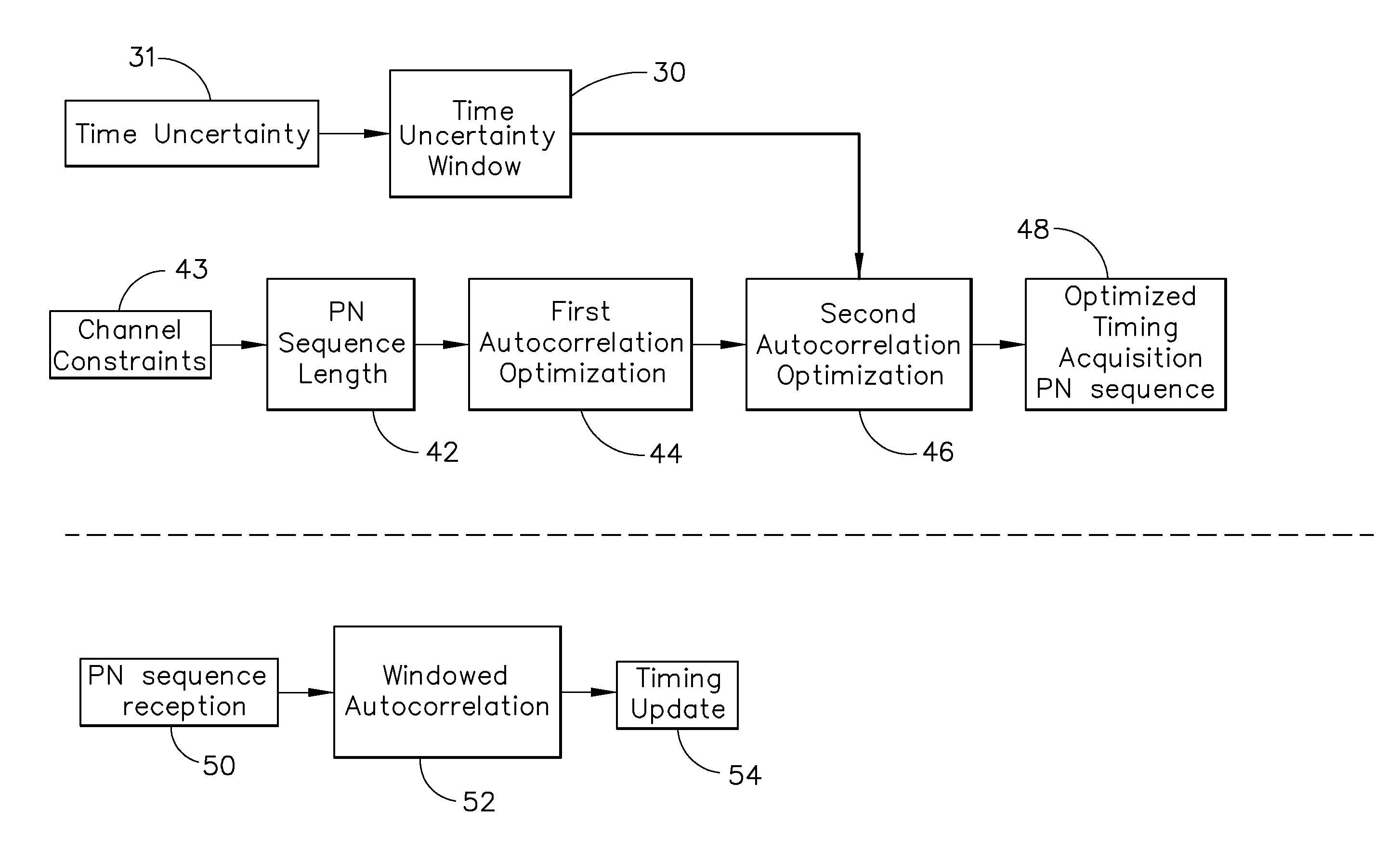
[0026]The timing acquisition process of the present invention includes selecting an initial sequence of complex numbers having preferred autocorrelation properties, and applying a two-step method to the initial sequence of complex numbers to enhance the autocorrelation properties of the initial sequence within a predetermined window defined by the bounded timing uncertainty of the system.

[0027]The timing acquisition process of the present invention preferably uses one or more computational or analytical processes to either generate a timing signal for transmission or detect a timing signal at a receiver. In one embodiment, the computational or analytical processes can be implemented by software stored in a memory device and executable by a microprocessor. The computational or analytical processes may also be implemented and executed using digital and / or analog hardware.

[0028]The system is implemented by selecting a complex number sequence (these would typically lie on the unit circl...


PUM


Abstract

A method of processing a timing synchronization signal includes selecting an initial sequence of complex numbers and modifying the initial sequence based upon a metric applied to the autocorrelation function to enhance its autocorrelation properties within a predetermined window about the main autocorrelation peak determined by the timing uncertainty of the system. This two-step optimization process produces a new complex sequence used for timing acquisition. It is applied by transmitting the sequence through a medium and correlating the received signal against a known error-free sequence. Only correlation within the window of the bounded timing uncertainty is performed, thus saving valuable computational cycles. Also, because the sidelobe levels of the autocorrelated function are significantly lower within the timing uncertainty window than the sidelobe levels of a non-optimized autocorrelation function of a signal, the likelihood of finding a peak for the wrong timing signal is greatly reduced.

Description

BACKGROUND OF THE INVENTION[0001]The present invention relates generally to a timing acquisition or synchronization method using pseudo-noise (PN) sequences. More particularly, the present invention provides a method for timing acquisition that is based on a bounded timing uncertainty.[0002]Timing acquisition and synchronization is a critical element of many modem electronic systems, such as Digital Communications Systems, Radar Systems, and Digital Signal Processing Systems. The subject of receiver synchronization is discussed in most books on digital communications (see, for example, Sklar, B, Digital Communications, 2nd Ed., Chapter 10, Prentice Hall, Upper Saddle River, N.J., 2001), and, indeed, entire books have been written on the subject of receiver synchronization within digital communications systems (Mengali, U, Synchronization Techniques for Digital Receivers, Springer, New York, N.Y., 1997; Meyr, H. et al, Synchronization in Digital Communications, John Wiley & Sons, Hob...

Claims


Application Information

Patent Timeline
Patent Type & Authority Patents(United States)
IPC IPC(8): H04L27/06H03D1/00H04L7/00H04L7/06
CPCH04B1/70754H04B1/7077
Inventor RAY, GARY A.BAKER, JAMES B.
Owner THE BOEING CO
Why Eureka
Try Eureka