Method for assembling a magnetic field generator for MRI

a magnetic field and generator technology, applied in the field of assembling a magnetic field generator for an mri, can solve the problems of difficult to fit each of the magnet blocks snugly to adjacent magnet blocks, difficult to place material blocks first and then magnetize each, and difficult to adjust with a lot of sub-steps, so as to achieve efficient assembly, efficient assembly and accurate

Inactive Publication Date: 2006-06-27
SUMITOMO SPECIAL METAL CO LTD
View PDF19 Cites 80 Cited by
  • Summary
  • Abstract
  • Description
  • Claims
  • Application Information

AI Technical Summary

Benefits of technology

[0029]According to this invention, the permanent magnet used for the magnetic field generator for MRI can be assembled efficiently. Further, the magnet unit and the column yoke can be assembled efficiently and accurately. As a result, the magnetic field generator for MRI can be assembled efficiently.

Problems solved by technology

It is very difficult to place material blocks first and then magnetize each.
Further, pole pieces for correcting the ununiformity of the magnetic field may be tilted to produce ununiformity in the magnetic field.
However, if the magnet blocks are mounted according to the above method, the ununiformity of the magnetic field is so large that the adjustment becomes very time consuming with a lot of sub-steps.
Further, according to the above method of bonding the magnet blocks, the magnet blocks each having a very intense magnetism have to be placed from above, onto the upper surface of the plate yoke, making extremely difficult to fit each of the magnet blocks snugly to adjacent magnet blocks.
For a conventional holding mechanism, it is very difficult to fit the magnet block snugly to the place of bonding efficiently against these strong forces.
Thus, when the column yoke is connected to the magnet unit, the column yoke is brought under the pulling force from the magnet unit, making difficult to connect the two at a high accuracy.
Likewise, when the second magnetic unit is connected to the column yoke already connected to the first magnet unit, it is also difficult to connect the two at a high accuracy.

Method used


Image

  • Method for assembling a magnetic field generator for MRI
  • Method for assembling a magnetic field generator for MRI
  • Method for assembling a magnetic field generator for MRI

Examples


Embodiment Construction

[0047]Now, preferred embodiments of this invention will be described with reference to the accompanying drawings.

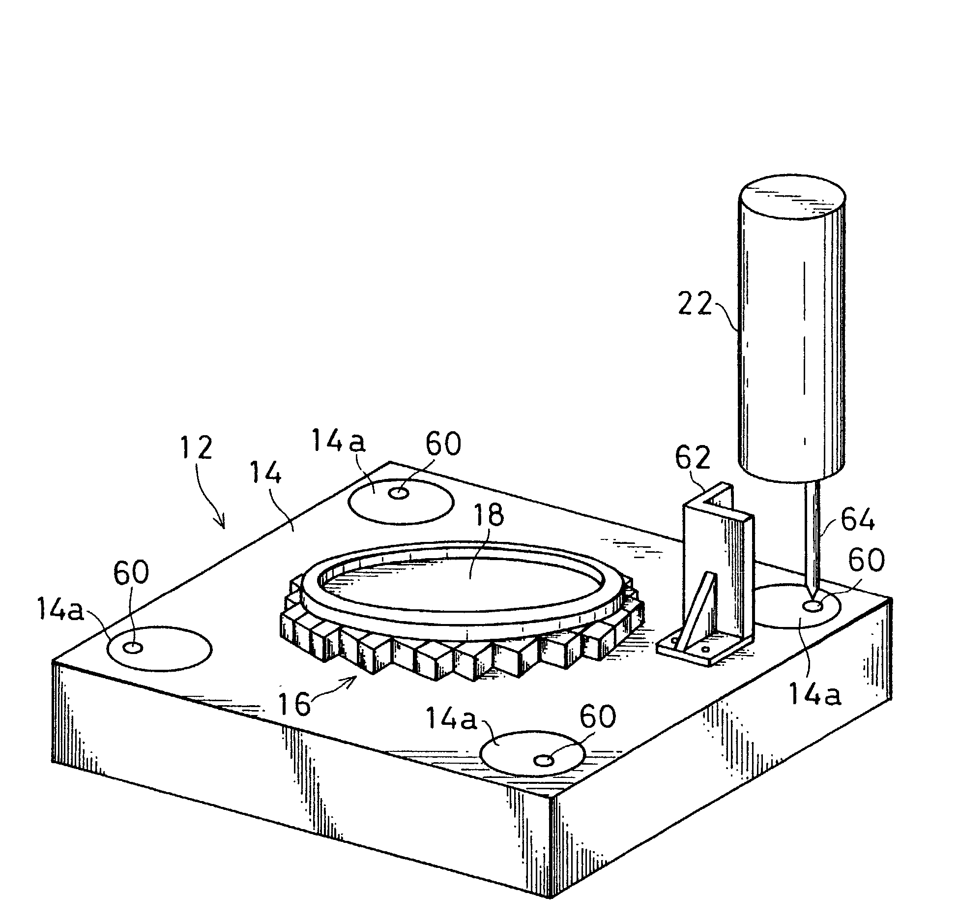
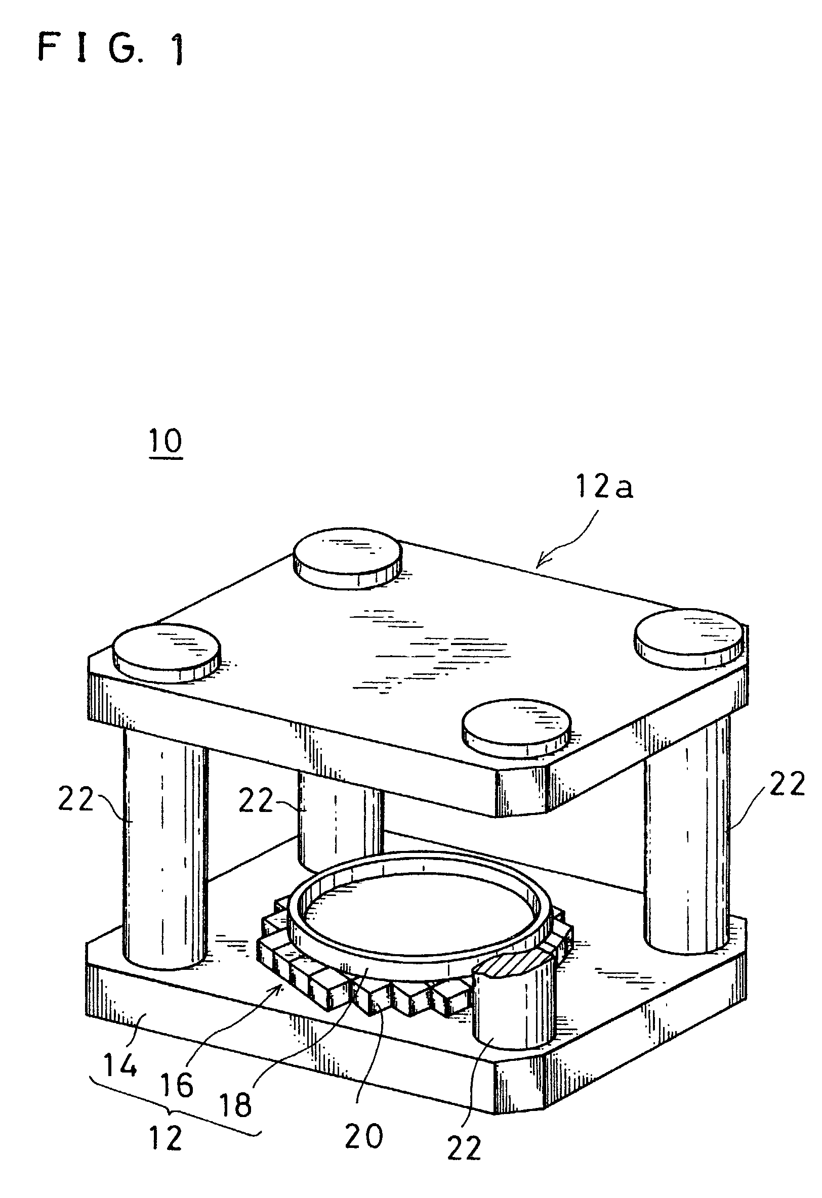
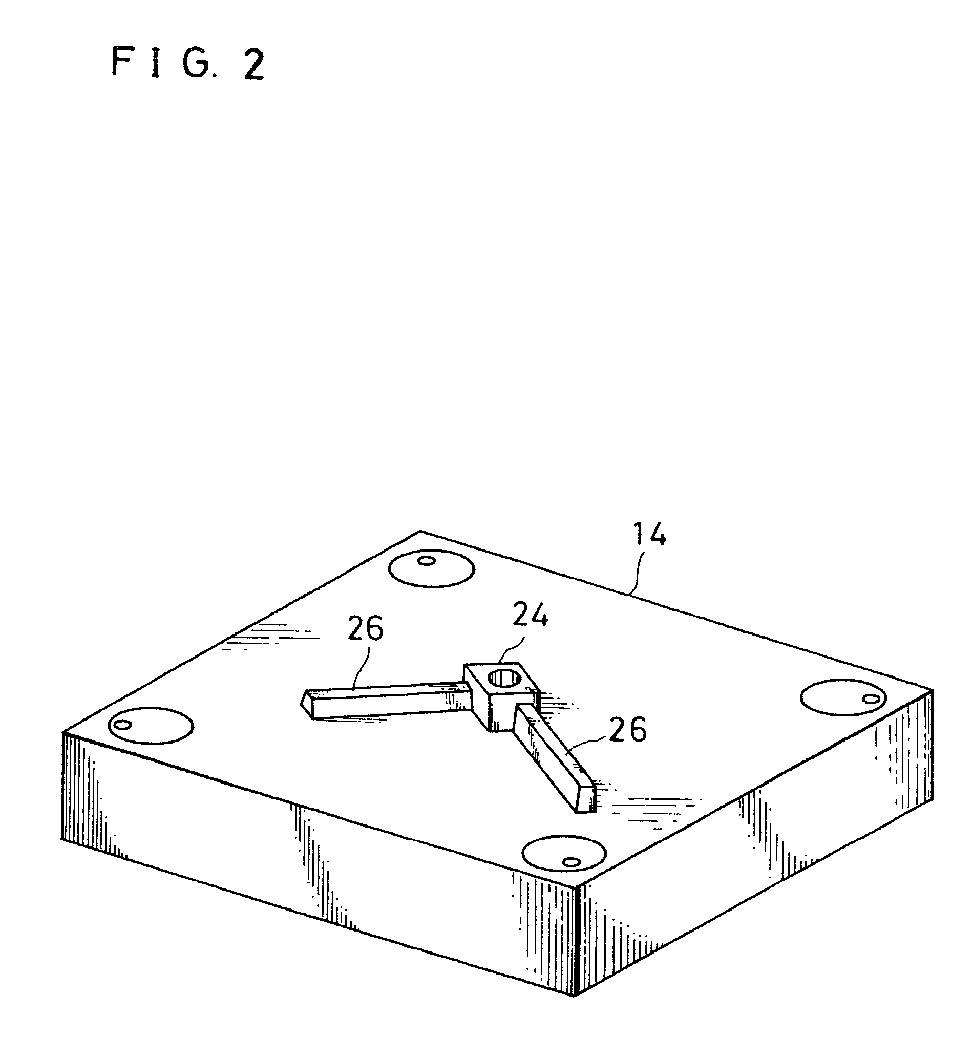
[0048]Referring first to FIG. 1, a magnetic field generator for MRI 10 as an embodiment of this invention comprises a pair of magnet units 12, 12a. Each of the magnet units 12, 12a includes a plate yoke 14. Each of the plate yokes 14 has a surface opposed to the other plate yoke, and this surface is provided with a permanent magnet 16, on which a pole piece 18 is provided. Each of the permanent magnets 16 includes a plurality of magnet blocks 20. Each of the magnet blocks 20 of the magnet unit 12 is fitted with adjacent ones, with a same magnetic pole facing upward. On the other hand, each of the magnet blocks 20 of the magnet unit 12a is fitted with adjacent ones, with the other magnetic pole facing downward. In other words, the permanent magnet 16 of the magnet unit 12 and the permanent magnet 16 of the magnet unit 12a are faced to each other so that different magnetic ...


PUM

PropertyMeasurementUnit
heightaaaaaaaaaa
angleaaaaaaaaaa
distanceaaaaaaaaaa

Abstract

A plate yoke has an upper surface formed with a projection and a guiding rail. A new magnet block is transported by sliding on the upper surface of the plate yoke, and is bonded side by side with the projection or a magnet block which is already fixed. During the above operation, a magnetic member is held above the plate yoke. Preferably, the new magnet block is transported toward a corner portion, with side surfaces of the magnet block held parallel to a side surface of the projection and a side surface of the guiding rail respectively. When the magnet unit and the column yoke is connected, the column yoke or the magnet unit is lowered so that a guiding rod attached to an end face of the column yoke is inserted into a hole formed in the magnetic unit. Further, the column yoke is guided by a guiding member disposed between a permanent magnet on the plate yoke and a position where the column yoke is to be connected on the plate yoke.

Description

[0001]This is a division of application Ser. No. 09 / 815,008 filed Mar. 23, 2001, now U.S. Pat. No. 6,650,214, which is a division of application Ser. No. 09 / 366,563 filed Aug. 4, 1999, now U.S. Pat. No. 6,336,989.BACKGROUND OF THE INVENTION[0002]1. Field of the Invention[0003]This invention relates to a magnetic field generator for an MRI, a method for assembling the same, and a method for assembling a magnet unit for the same. More Specifically, this invention relates to a magnetic field generator for MRI incorporating permanent magnets, a method for assembling the same, and a method for assembling a magnet unit for the same.[0004]2. Description of the Related Art[0005]A magnetic field generator for MRI uses permanent magnets. The magnet used in such an apparatus have to be made up of a plurality of magnet blocks. It is very difficult to place material blocks first and then magnetize each. Thus, in actual manufacturing, the magnetized blocks must be aligned on a plate yoke so that ...

Claims


Application Information

Patent Timeline
Patent Type & Authority Patents(United States)
IPC IPC(8): H01F7/06A61B5/055G01R33/38G01R33/383H01F7/02
CPCG01R33/3806G01R33/383G01R33/3802Y10T29/4902Y10T29/49075Y10T29/49902Y10T29/49002Y10T156/1089Y10T29/49073Y10T29/49901
Inventor AOKI, MASAAKIHASHIMOTO, SHIGEO
Owner SUMITOMO SPECIAL METAL CO LTD
Why Eureka
Try Eureka