Method and apparatus for breakaway mounting of security gate to drive mechanism

a technology of security gate and drive mechanism, which is applied in the direction of traffic signals, traffic gates, ways, etc., can solve the problems of gate being drive mechanism damage, gate may be forced into unintended movement,

Inactive Publication Date: 2006-06-27
THE CHAMBERLAIN GRP INC
View PDF9 Cites 8 Cited by
  • Summary
  • Abstract
  • Description
  • Claims
  • Application Information

AI Technical Summary

Benefits of technology

[0004]FIG. 1 shows a perspective view of an example of a known security gate drive mechanism;

Problems solved by technology

Commonly, a drive mechanism may be severely damaged if the gate is prevented from being moved in the direction that the drive mechanism is trying to move the gate, e.g., if some obstacle, like a vehicle, is blocking the intended movement of the security gate.
In addition, even if the gate is not currently in motion and being driven by the gate driving mechanism, the gate may be forced into unintended movement, as, e.g., by a collision with a vehicle, e.g., attempting to breach the security gate and gain unauthorized ingress or egress.
Under these circumstances, the security gate drive mechanism may be bent or broken, e.g., by the arm being bent of the drive screw for a linear drive mechanism becoming bent or broken.
In addition, the driving motor attached to the gate may be broken.
This is particularly a problem with security gate drive mechanisms that swing a security gate from an open position to a closed position and vice-versa.

Method used


Image

  • Method and apparatus for breakaway mounting of security gate to drive mechanism
  • Method and apparatus for breakaway mounting of security gate to drive mechanism
  • Method and apparatus for breakaway mounting of security gate to drive mechanism

Examples


Embodiment Construction

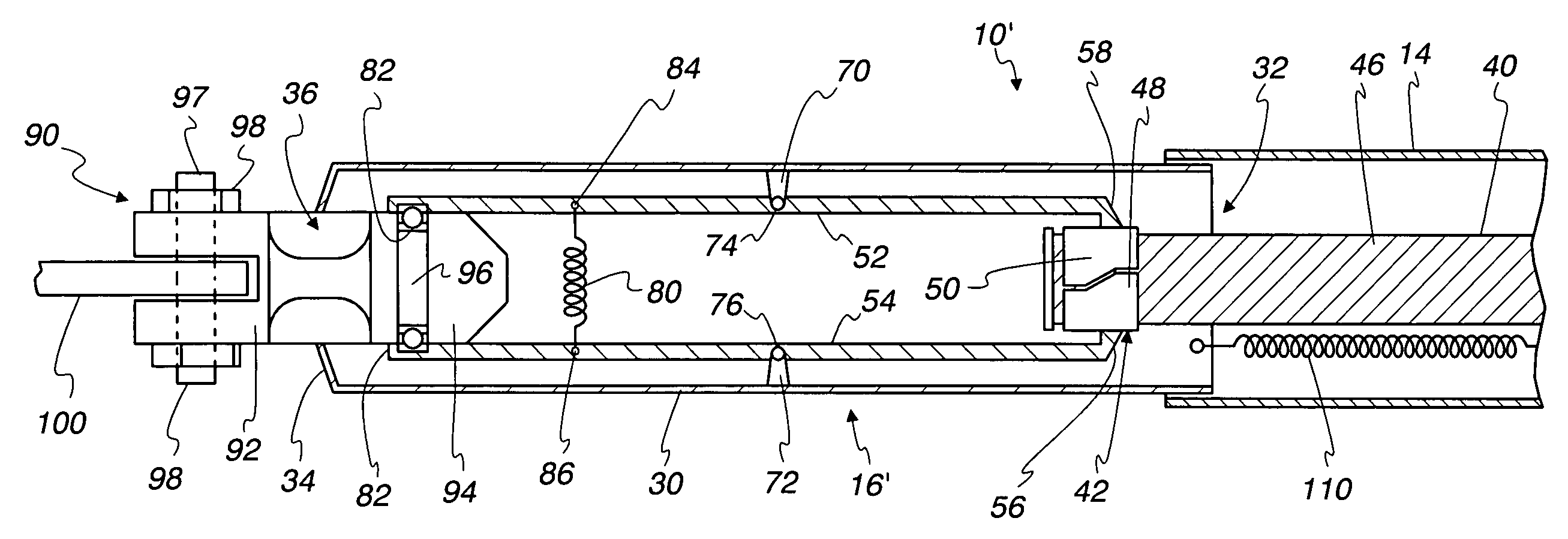
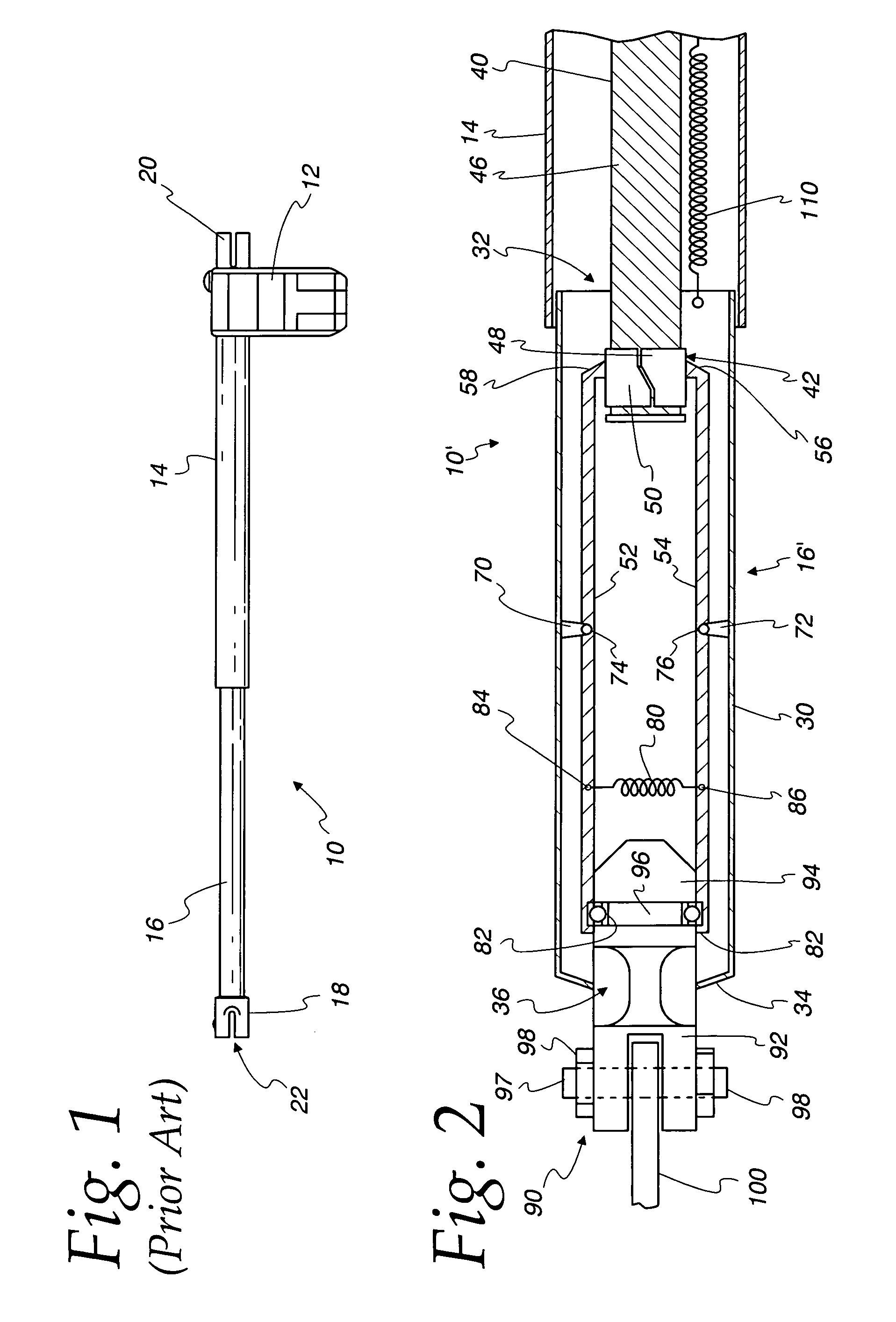
[0007]Turning now to FIG. 1 there is shown a known example of a security gate operating mechanism 10 according to the prior art. The security gate operating mechanism can include a drive motor housing 12, which can contain a drive motor (not shown) for example an electrically driven rotating gear motor that can drive a threaded screw (not shown) contained within a generally tubular housing 14 an extensible arm 16 may be driven by the threaded screw, e.g., by being attached to a carriage (not shown) that moves along the threaded screw in response to the rotation of the rotating gear of the motor. Attached essentially rigidly to the distal end of the extensible arm 16 may be a gate attachment member 18, which may have a slot 22 for receiving a security gate attachment bracket (not shown) that can be mounted on the security gate, and can be rotatably attached to the security gate attachment bracket, e.g., by an attachment bolt that extends through a hole (not shown) in the attachment m...


PUM


Abstract

A method and apparatus for operating a security gate is disclosed which may comprise a drive mechanism arm having a first end and a second end, and including a security gate attachment member connected to the first end of the drive mechanism arm; a drive mechanism actuator operatively connected directly or indirectly to the drive mechanism arm and adapted to move the drive mechanism arm along a predefined path in relation to the actuator in response to operation of the actuator; and a release mechanism adapted to release the connection of the security gate attachment member to the first end of the drive mechanism arm in response to the application of a force to the security gate attachment member in a direction other than the force applied to the security gate attachment member by the drive mechanism arm in response to the operation of the actuator to move the security gate drive mechanism arm along the predefined path. The apparatus and method may also include a retractor to retract the drive arm after disconnection. The apparatus and method may have an actuator is a linear motion actuator connected directly to the drive mechanism arm, or a rotary motion actuator indirectly connected to the drive mechanism arm.

Description

[0001]This application is a continuation of application Ser. No. 09 / 846,560 filed Apr. 24, 2001, now abandoned.FIELD OF THE INVENTION[0002]The present invention relates to the field of security gate driving mechanisms and more specifically to a method and apparatus for providing breakaway protection for a security gate drive mechanism.BACKGROUND OF THE INVENTION[0003]It is known to provide security gates that a driven by a motor operated control arm that may be articulated or linear in nature. Commonly, a drive mechanism may be severely damaged if the gate is prevented from being moved in the direction that the drive mechanism is trying to move the gate, e.g., if some obstacle, like a vehicle, is blocking the intended movement of the security gate. In addition, even if the gate is not currently in motion and being driven by the gate driving mechanism, the gate may be forced into unintended movement, as, e.g., by a collision with a vehicle, e.g., attempting to breach the security gat...

Claims


Application Information

Patent Timeline
Patent Type & Authority Patents(United States)
IPC IPC(8): E05B65/10E01F13/00E01F9/00E05F15/00E05F15/12
CPCE05F15/622E05F15/41E05Y2900/40B61L29/04
Inventor PARSADAYAN, WALTERHOM, WAYNE C.
Owner THE CHAMBERLAIN GRP INC
Why Eureka
Try Eureka