
Torque-setting, tamper-resistant fastener and method and tool for use with same

a technology of tamper-resistant fasteners and torque-setting, which is applied in the field of tamper-resistant fasteners, can solve the problems of difficult manufacturing of cam-like pockets or steps, difficult method of creating tamper-resistant fasteners, and difficulty in access

Inactive Publication Date: 2006-06-27
FLESHER ROBERT W
View PDF38 Cites 127 Cited by
  • Summary
  • Abstract
  • Description
  • Claims
  • Application Information

AI Technical Summary

Benefits of technology

The solution enhances manufacturing ease, reduces installation hazards, and ensures accurate torque application, maintaining assembly integrity while discouraging unauthorized removal.

Problems solved by technology

While it is impossible to stop a determined thief, most applications of tamper-resistant technology require only that access be made very difficult unless a special tool is used.
It is apparent that this method of creating a tamper-resistant fastener relies on the relative scarcity of installation tools.
Modifying the head of a fastener to incorporate offset holes, cam-like pockets or steps proves difficult to manufacture due to the high tolerances that must be held.
As a result, the price of tamper-resistant fasteners is high.
By necessity, the installation tools are encumbered with a complex, and often quite sharp or dangerous, tool tip.
This becomes a hazard during installation when torque is applied and the tool tip cams out of the fastener head and skids across the articles being joined.
This situation is highly undesirable, dangerous and happens far too often using existing designs.
Cam-out is a major problem for manufacturers that focus on product quality such as the auto industry.
A further problem with standard and tamper-resistant fasteners relates to the inability to accurately torque down the fastener during install.
Stretching or compression of the spring over time introduces inaccuracies to the torque measurement.

Method used


Image

  • Torque-setting, tamper-resistant fastener and method and tool for use with same
  • Torque-setting, tamper-resistant fastener and method and tool for use with same
  • Torque-setting, tamper-resistant fastener and method and tool for use with same

Examples


Embodiment Construction

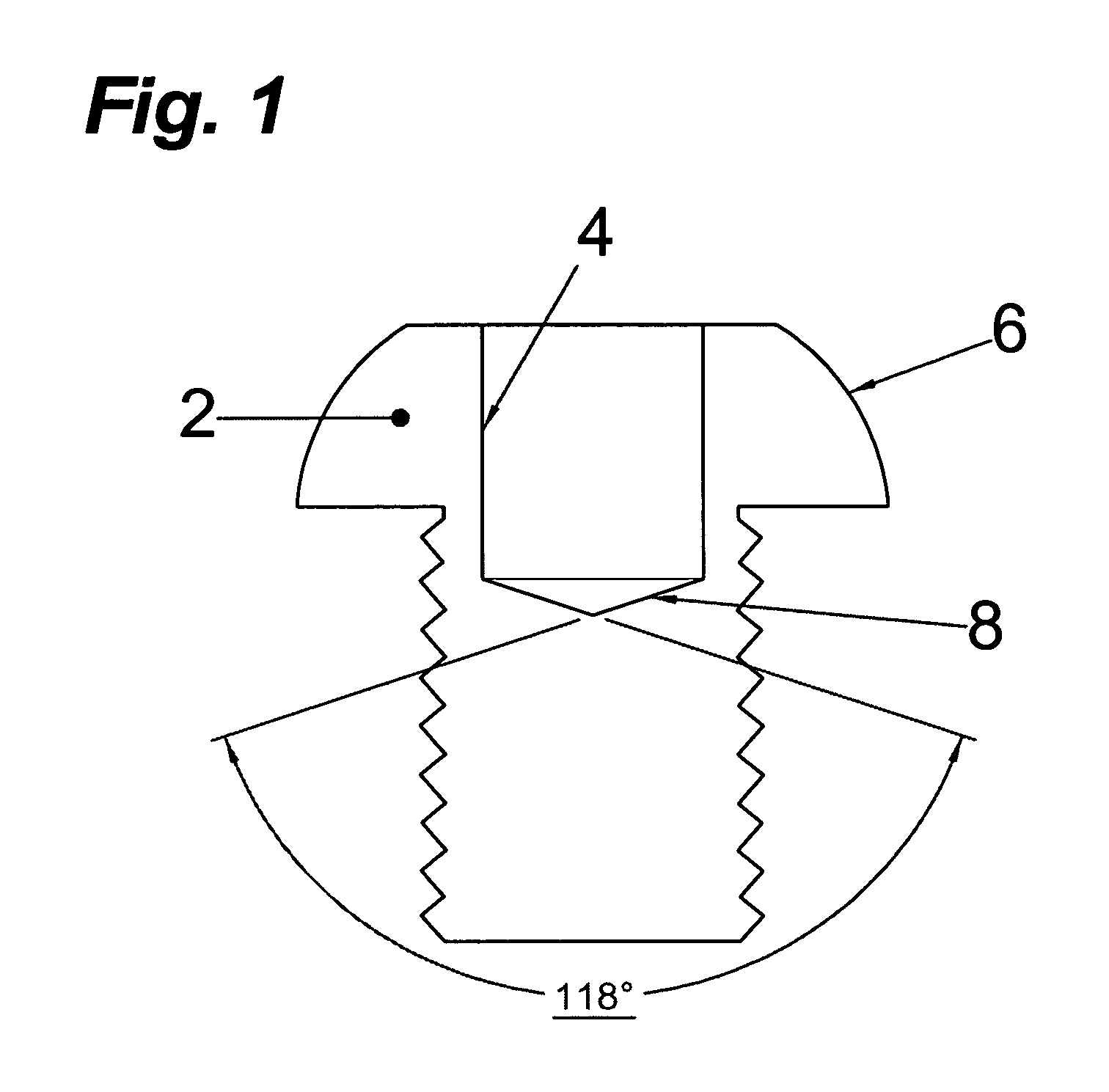
[0034]In accordance with an embodiment of the present invention, a fastener incorporates a smooth-sided pocket (or bore) in the fastener head on centerline with the threads that can be made using a standard drill bit. A feature of this embodiment is a tamper-resistant fastener head geometry that may be adapted to various fasteners. The tamper-resistant fastener cannot be operated with conventional tools. A further feature of this embodiment is a fastener head geometry and installation tool that allows high installation torque with correspondingly high axial friction thereby preventing cam-out. The installation tool is easy to construct and can be adapted for either manual or automated use.

[0035]Another embodiment of the invention provides a fastener that can be precisely torqued to a desired value by virtue of a shear pin either on the installation tool or on the fastener itself.

[0036]A feature of an embodiment of this invention is a tamper-resistant fastener that can be used more t...


PUM


Abstract

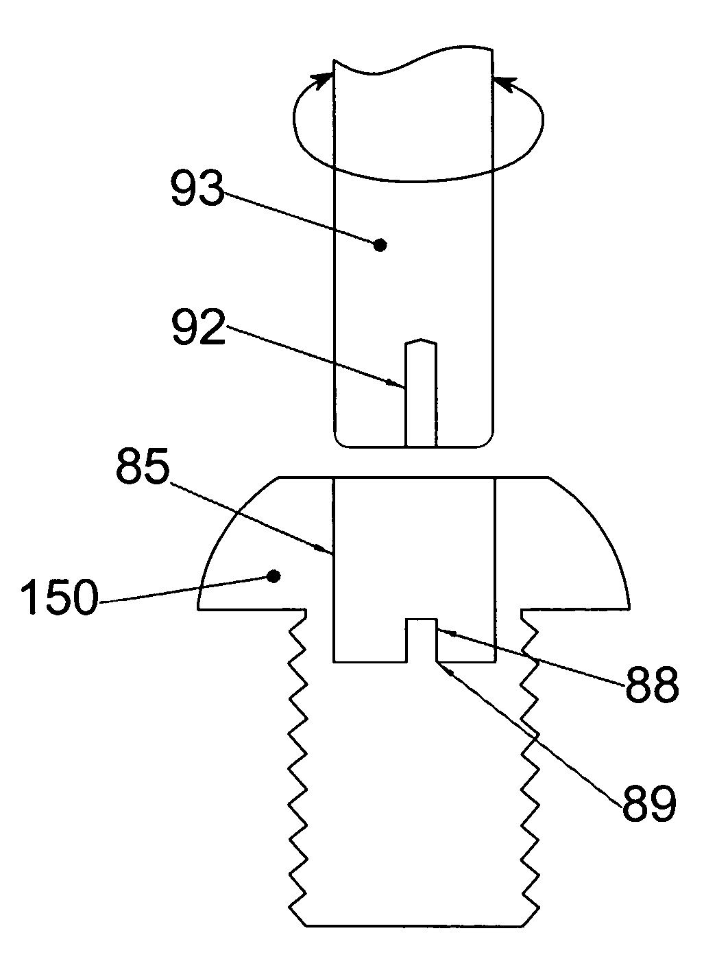
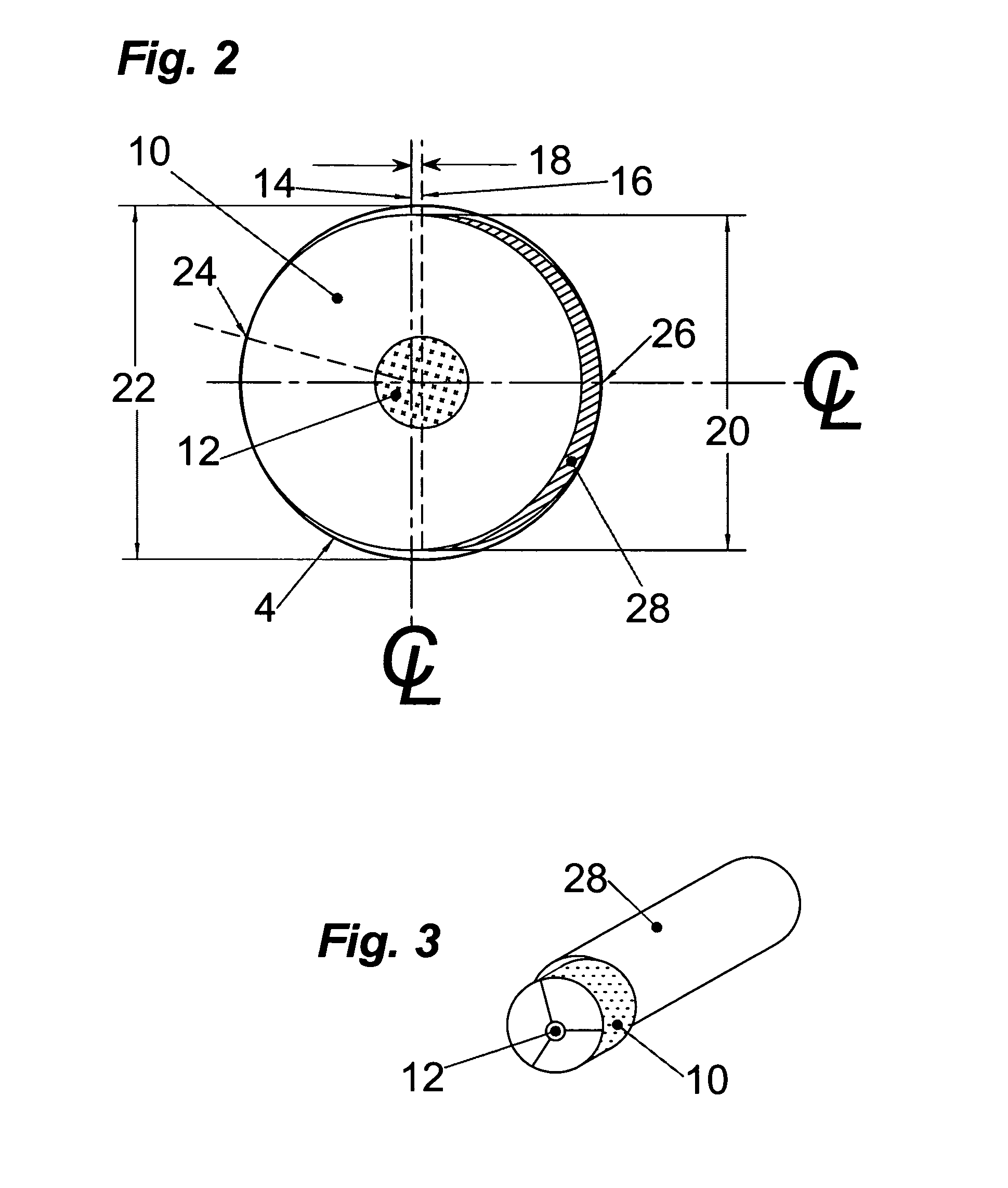
A fastener includes a round, blind hole or pocket in its head. Installation and removal of the fastener is accomplished with a tool containing an eccentric segment on the end of a shaft. When rotated within the pocket, the eccentric segment displaces laterally relative to the shaft to provide a friction grip to the lateral wall of the pocket. The strength of the grip is proportional to the applied torque. Eccentric displacement allows rotation but prevents the tool from spinning out of the fastener thereby eliminating cam-out and surface damage resulting from contact with a spinning tool tip. The eccentric head of the tool can be made disposable and to shear off when a predetermined torque is reached. The smooth-sided round hole offers no purchase for commonly available tools; making the fastener tamper-resistance. In another embodiment, the fastener includes a raised portion in the pocket. A tool having a complementary opening shears off the raised portion at a predetermined torque.

Description

BACKGROUND OF THE INVENTION[0001]1. Field of the Invention[0002]The present invention relates to the field of fasteners and, more particularly, to tamper-resistant fasteners (e.g., bolts) and to fasteners requiring tightening to a precise torque.[0003]2. Related Art[0004]In many instances it is necessary to prevent unauthorized intrusion or disassembly of a product in order to prevent theft or injury. Use of such fasteners on medical equipment ensures that unskilled individuals will not attempt adjustments. Use on cable set-top boxes prevents tampering with the electronics within. Use on public structures such as playground equipment, picnic benches, and on restroom fixtures prevents theft and disassembly-type vandalism.[0005]While it is impossible to stop a determined thief, most applications of tamper-resistant technology require only that access be made very difficult unless a special tool is used. To accomplish this, prior designs modified the heads of commonly used bolts and sc...

Claims


Application Information

Patent Timeline
Patent Type & Authority Patents(United States)
IPC IPC(8): B25B23/08F16B23/00B25B13/48B25B15/00B25B23/00F16BF16B31/02F16B35/06F16B41/00
CPCB25B13/485F16B23/0023F16B23/0069F16B31/021F16B23/0046F16B41/005
Inventor FLESHER, ROBERT W.
Owner FLESHER ROBERT W
Learn More