Casing mandrel with well stimulation tool and tubing head spool for use with the casing mandrel

a well stimulation and casing mandrel technology, which is applied in the direction of drilling casings, well accessories, drilling pipes, etc., can solve the problems of time-consuming operation, unsatisfactory situation, and idle crews, and achieve rapid and efficient completion or re-complete. , the effect of improving safety

Inactive Publication Date: 2006-06-27
WELLS FARGO BANK NAT ASSOC +1
View PDF35 Cites 92 Cited by
  • Summary
  • Abstract
  • Description
  • Claims
  • Application Information

AI Technical Summary

Benefits of technology

[0021]The system in accordance with the invention therefore provides a safe, efficient set of components for an independent screwed wellhead that permits a well equipped with the wellhead to be rapidly and efficiently completed or re-completed, while ensuring that stresses on the well stimulation tool and wellhead components do not exceed engineered limits. Safety is therefore significantly improved. In addition, full-bore access permits multi-zone completion or re-completion without cost-incurring delays associated with prior art methods of completing or re-completing such wells.

Problems solved by technology

This is an undesirable situation.
Furthermore, use of a casing saver to perform well completion or re-completion slows down operations in a multi-zone well because the flow rates are hampered by the reduced internal diameter of the casing saver.
It is well known in the art that the disconnection of fracturing lines and the removal of a casing saver is a time consuming operation that keeps expensive fracturing equipment and / or wireline equipment and crews setting idle.

Method used


Image

  • Casing mandrel with well stimulation tool and tubing head spool for use with the casing mandrel
  • Casing mandrel with well stimulation tool and tubing head spool for use with the casing mandrel
  • Casing mandrel with well stimulation tool and tubing head spool for use with the casing mandrel

Examples


first embodiment

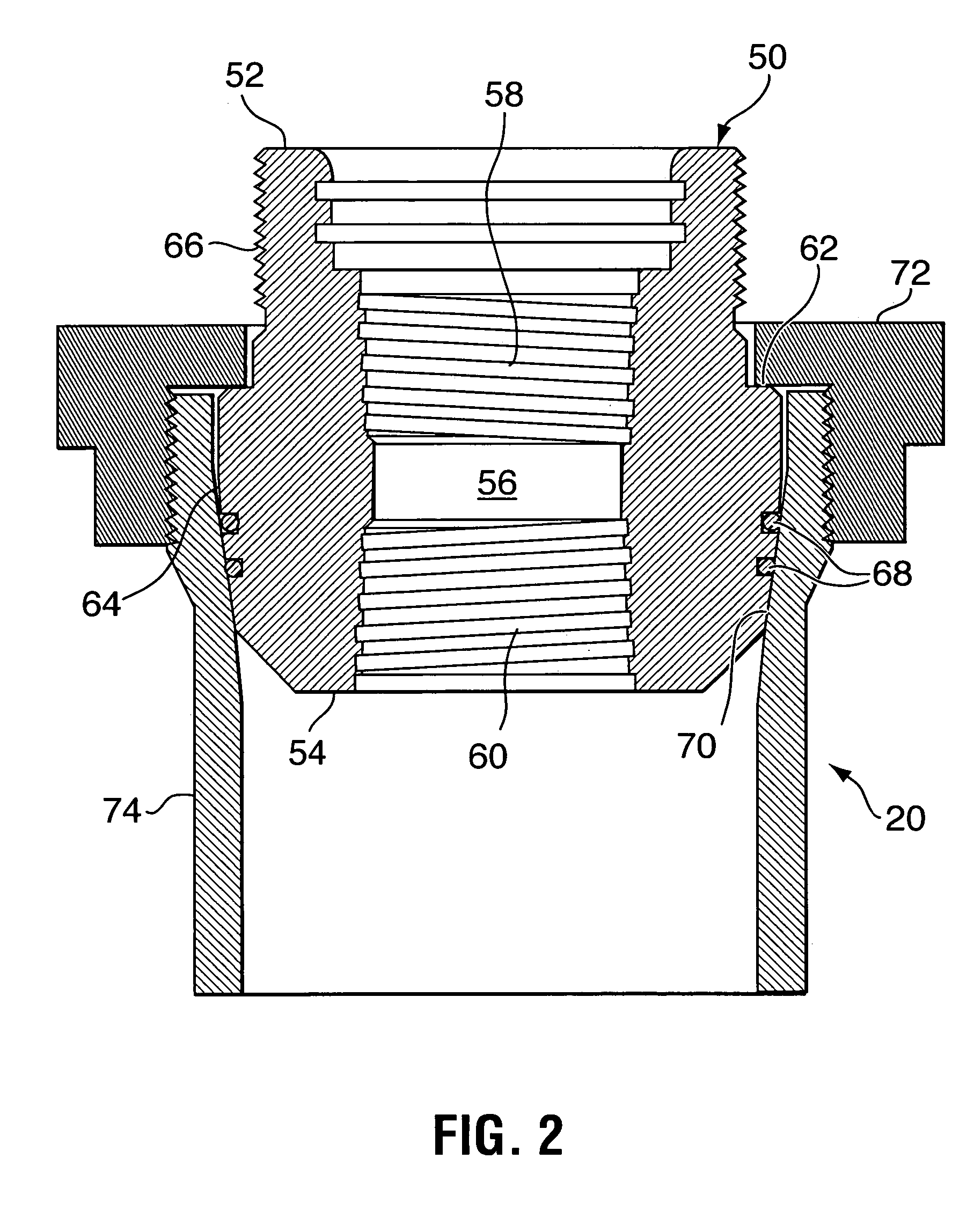
[0035]FIG. 3a is a cross-sectional schematic view of a well stimulation tool in accordance with the invention connected to the casing mandrel 50 shown in FIG. 2. The independent screwed wellhead 20 is mounted to a surface casing 74 in a manner well known in the art. A production casing 76 having an internal diameter 78 threadedly engages the box thread 60 of the casing mandrel 50. A well stimulation tool 80 is mounted to a top of the casing mandrel 50. The well stimulation tool 80 includes a well stimulation tool mandrel 82 with a bottom end 83 having a pin thread 85 that engages the top end box thread 58 of the casing mandrel 50. The well stimulation tool mandrel 82 has an internal diameter 86 that is the same as the internal diameter 78 of the production casing 76. The well stimulation tool mandrel 82 also has a top flange 88 to which a well fracturing assembly, commonly referred to as a “fracstack” is mounted, in a manner well known in the art. The well stimulation tool mandrel 8...

second embodiment

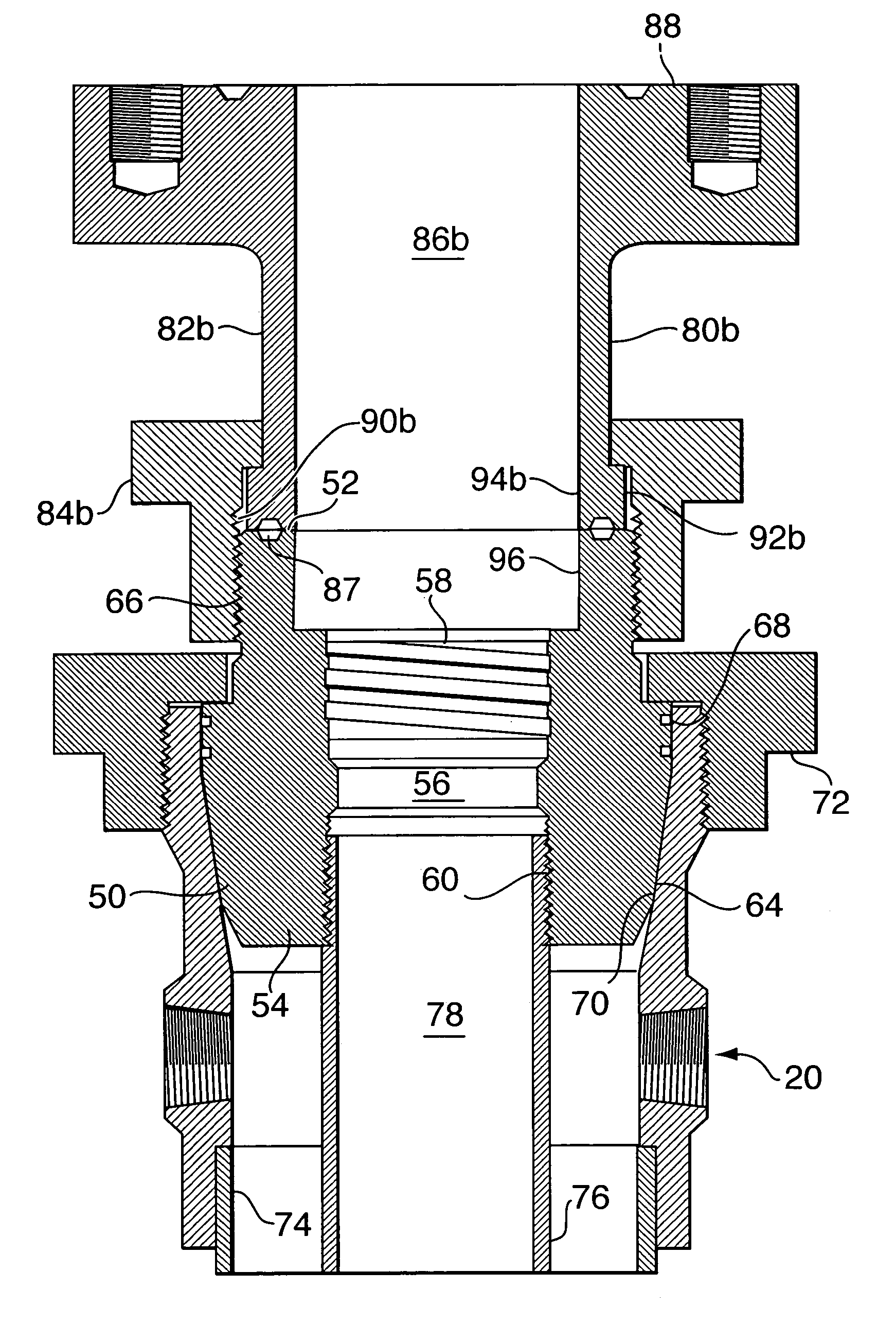
[0038]FIG. 3b illustrates the well stimulation tool in accordance with the invention connected to the casing mandrel 50 shown in FIG. 2. The well stimulation tool 80b is mounted to a top of the casing mandrel 50. The well stimulation tool 80b includes a well stimulation tool mandrel 82b with a bottom end 94b that includes an annular groove that mates with an annular groove 87 in the top end of the casing mandrel 50 for accommodating a high-pressure fluid seal, such as a ring gasket, which is well known in the art. The well stimulation tool mandrel 82b has an internal diameter 86b that is the same as an internal diameter of the secondary seal bore 96. The well stimulation tool mandrel 82 also has a top flange 88b to which a blowout preventer (not shown) can be mounted. A blowout preventer protector (not shown) is mounted to a top of the blowout preventer as described in co-applicant's U.S. Pat. No. 6,364,024, which issued Apr. 2, 2002, the specification of which is incorporated herei...


PUM


Abstract

A casing mandrel for an independent screwed wellhead includes a pin thread adapted for engagement with a box thread of a well stimulation tool lockdown nut for securing the well stimulation tool against the casing mandrel top end. A well stimulation tool and a tubing head spool for use with the casing mandrel are also provided. Safety of well stimulation procedures is thereby improved and well completion time is significantly reduced.

Description

CROSS-REFERENCE TO RELATED APPLICATIONS[0001]This application claims priority to Canadian Patent Application No. 2,428,613, filed in Canada with the Canadian Intellectual Property Office on May 13, 2003.MICROFICHE APPENDIX[0002]Not Applicable.TECHNICAL FIELD[0003]The present invention relates generally to wellhead assemblies and, in particular, to a casing mandrel with a well stimulation tool and tubing head spool for use with the casing mandrel to improve the safety of well stimulation procedures on wells equipped with independent screwed wellheads.BACKGROUND OF THE INVENTION[0004]Independent screwed wellheads are well known in the art and classified by the American Petroleum Institute (API). The independent screwed wellhead has independently secured heads for each tubular string supported in the well bore. Independent screwed wellheads are widely used for production from low-pressure productions zones because they are economical to construct and maintain.[0005]It is well known in ...

Claims


Application Information

Patent Timeline
Patent Type & Authority Patents(United States)
IPC IPC(8): E21B33/04E21B33/068
CPCE21B33/068E21B33/04
Inventor DALLAS, L. MURRAYMCGUIRE, BOB
Owner WELLS FARGO BANK NAT ASSOC
Why Eureka
Try Eureka