

Golf club head
Inactive Publication Date: 2006-06-27
DUNLOP SPORTS CO LTD
View PDF6 Cites 67 Cited by
- Summary
- Abstract
- Description
- Claims
- Application Information
AI Technical Summary
Benefits of technology
[0004]It is therefore, an object of the present invention to provide a golf club head, in which the fa
Problems solved by technology
In this case, even if a material having flexure strength is used, it is difficult to provide sufficient durability for the impact area or the central portion of the clubface.
In this case to
Method used
View moreImage
Smart ImageViewing Examples

Examples
 PUM
 Abstract
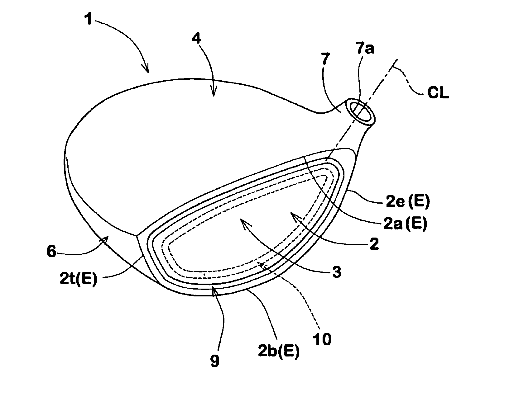
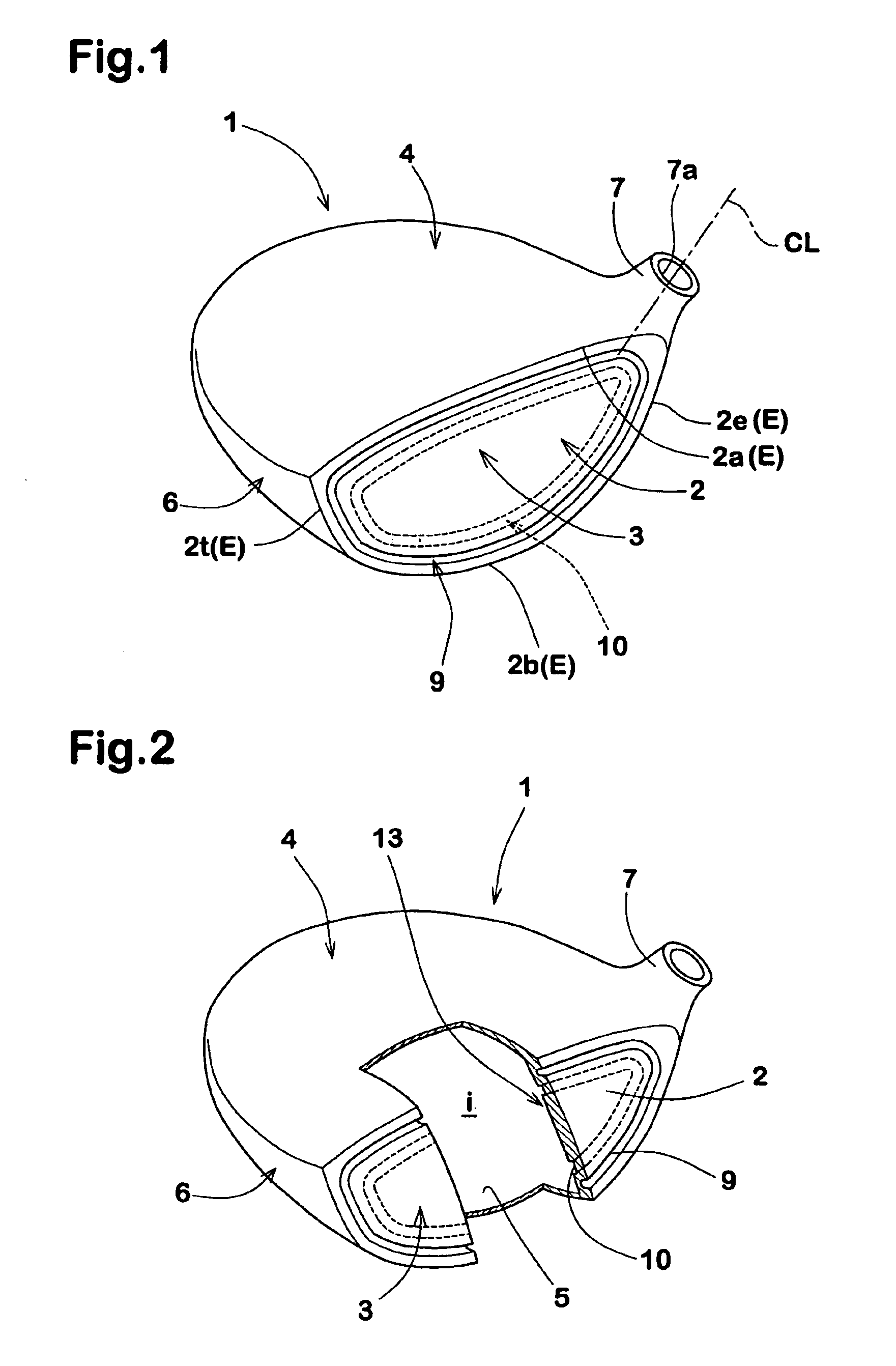
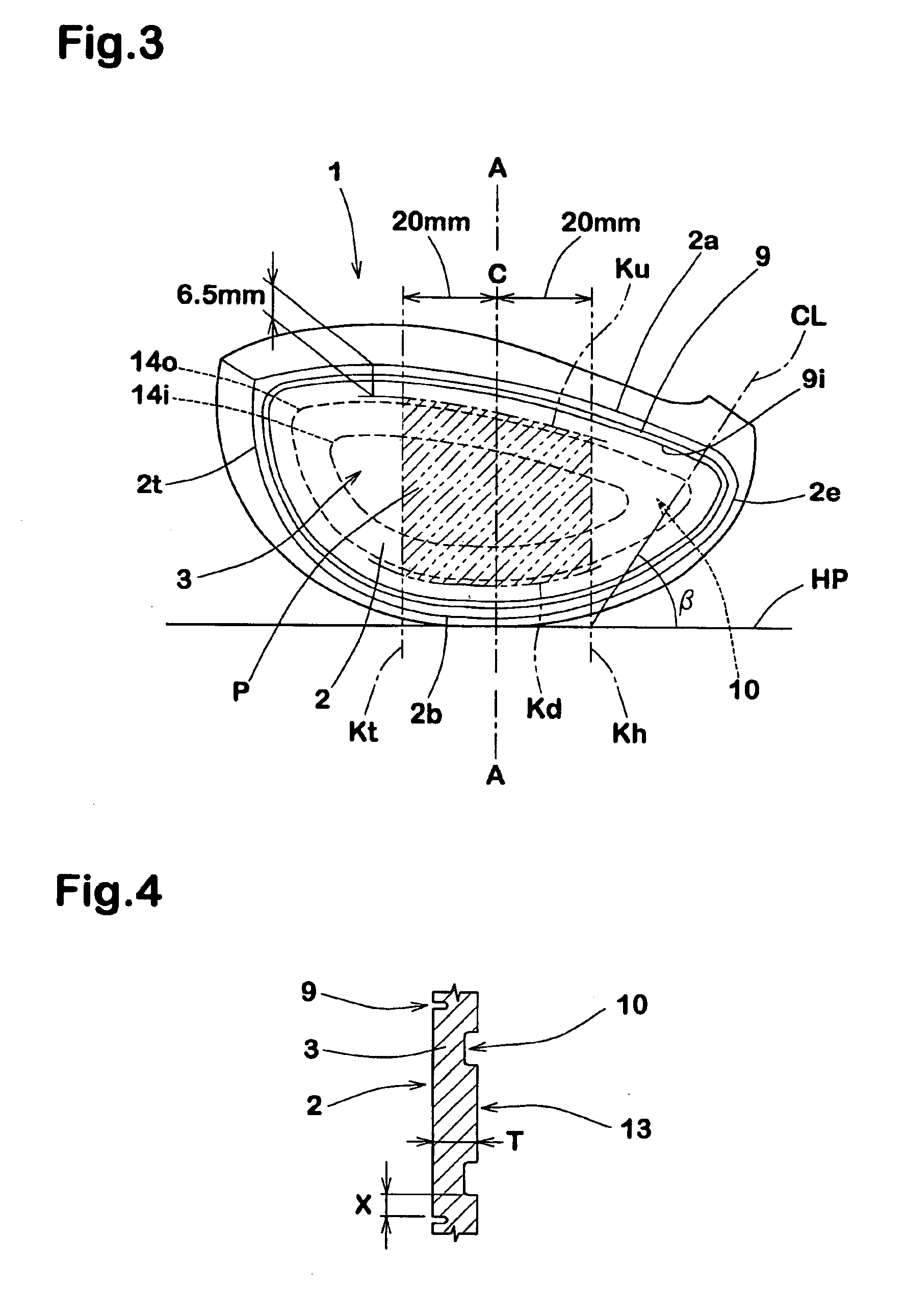
A golf club head comprises a face portion having a front face defining a clubface for hitting a ball and a back face facing a hollow, wherein the clubface is provided along the edge thereof with a frontal groove having a groove width of not less than 0.5 mm, and the back face is provided with a backside groove extending along the frontal groove.
Description
BACKGROUND OF THE INVENTION[0001]The present invention relates to a golf club head, more particularly to an improved structure of the face portion being capable of improving the coefficient of restitution.[0002]In order to increase the carry of the struck ball, various improvements have been made on the face portion of a golf club head for the purpose of increasing the coefficient of restitution of the face portion.[0003]In case of a golf club head having a hollow behind the face portion, for example, the face portion is made using a thin metal material to improve the flexure when hitting a ball. In this case, even if a material having flexure strength is used, it is difficult to provide sufficient durability for the impact area or the central portion of the clubface. In another design, therefore, to achieve a high restitution coefficient and durability at the same time, a groove is formed on the periphery of the back face of the face portion to leave the impact area thicker. In thi...
Claims
Login to View More Application Information
Patent Timeline
 IPC IPC(8): A63B53/04A63B102/32
CPCA63B53/04A63B49/06A63B53/0466A63B2053/0408A63B2053/0445A63B2053/045A63B53/0487A63B53/047A63B2053/0458A63B60/52A63B53/0445A63B53/0458A63B53/045A63B53/0408A63B60/00
InventorYAMAMOTO, AKIO
OwnerDUNLOP SPORTS CO LTD